What is The Spray Rating Tester For Protective Clothing GT-C31
In industries where protective clothing is essential, ensuring the garments' water resistance plays a crucial role in determining their durability and effectiveness. The Spray Rating Tester For Protective Clothing GT-C31 is a vital tool in evaluating the water repellency of protective fabrics. It simulates real-world conditions by spraying water onto textile samples to assess their surface wetting resistance. This article will explore the importance of water repellency testing in protective clothing and provide an in-depth overview of the Spray Rating Tester GT-C31.
Importance of Water Repellency in Protective Clothing Protective clothing is widely used in sectors such as healthcare, firefighting, industrial work, and outdoor professions where exposure to water, chemicals, and hazardous substances is frequent. The ability of the fabric to repel water is critical because it ensures the wearer's safety by keeping harmful liquids at bay. The Spray Rating Tester GT-C31 provides an efficient method for determining how well fabrics perform in preventing surface wetting, which is especially important for garments exposed to rain or chemical splashes.
Understanding the Spray Rating Tester GT-C31 The Spray Rating Tester GT-C31 is designed specifically to simulate light rain conditions, allowing manufacturers and quality control professionals to measure fabric performance in repelling water. The tester uses a precise method to evaluate surface wetting by spraying water on a sample fabric at a controlled angle and height, as specified in international standards.
Step-by-Step Process of Spray Rating Testing To understand how the Spray Rating Tester GT-C31 works, let’s break down the test procedure into its key steps:
Step 1: Sample Preparation Begin by preparing a 180mm x 180mm textile sample. The textile should be representative of the material used in protective clothing to ensure accurate results. Once ready, the sample is installed on the fixture to secure it in place for testing.
Step 2: Securing the Sample The fixture with the textile sample is then fixed on the 45° test station. This angle ensures that water is sprayed in a manner that mimics natural rain hitting the fabric surface.
Step 3: Funnel and Baffle Placement A test funnel is placed in the fixed ring above the fixture, and a baffle plate is positioned in the center of the funnel. The baffle ensures that the water is distributed evenly across the textile sample during the test.
Step 4: Measuring Distance Next, measure the distance between the bottom of the funnel and the sample surface. The prescribed distance is 150mm, but this height can be adjusted based on specific testing requirements.
Step 5: Water Application Pour 250ml of distilled water into the funnel. The spray time is crucial and should fall between 25 and 30 seconds to ensure consistent results. The controlled flow rate replicates rain conditions that the protective clothing may encounter in the real world.
Step 6: Evaluation of Results Once the test is completed, remove the textile sample from the fixture and compare it against the standard rating cards. These cards help in assessing the water repellency of the sample based on the degree of surface wetting observed.
Why Choose the Spray Rating Tester GT-C31? The Spray Rating Tester GT-C31 offers a reliable and standardized method to evaluate water repellency in protective fabrics. It is widely used by manufacturers, research institutions, and testing laboratories due to its precision, ease of use, and adherence to international standards such as ISO and AATCC.
1. Precise Measurements: The Protective Clothing Spray Rating Tester ensures that each test is conducted under controlled and consistent conditions, leading to accurate and reliable results.
2 .Standardized Testing: It complies with international standards for water repellency testing, making the results widely accepted across industries.
The GT-LB06A Chair Front Stability Testing Machine is a specialized device designed to evaluate the forward stability of chairs, ensuring they can withstand everyday use. This article provides a comprehensive guide on how to operate the Chair Front Stability Testing Machine effectively, along with insights into its importance in product testing.
Introduction to the GT-LB06A Chair Front Stability Testing Machine The GT-LB06A Chair Front Stability Testing Machine is engineered to simulate the forces that a chair might encounter during normal usage. By understanding how to use this machine, manufacturers can ensure their products are safe and stable.
Step-by-Step Operation Guide
1. Preparation
Before beginning the testing process, make sure that you have the following:
2. Setting Up the Machine 2.1 Connect the Power Supply: Plug the machine into a suitable power outlet. Turn on the power switch to initiate the machine’s operation.
2.2 Marking the Chair: Take the chair you wish to test and mark the position of the loading point 60mm from the edge. This step is crucial for accurate testing, as it indicates where the force will be applied.
3. Preparing the Chair for Testing 3.1 Positioning the Loading Pad: Place the loading pad on the marked point. The center of the loading pad should align with the marked line on the chair. Secure the loading pad in place using string to prevent any movement during testing.
3.2 Mounting the Chair: Install and fix the chair onto the GT-LB06A Chair Front Stability Testing Machine. Make sure the chair is stable and securely mounted. Adjust the chair so that its center is aligned with the weights that will be applied during the test.
4. Setting Up the Weights 4.1 Adjusting the Chair Wheels: Ensure the chair wheels are positioned close to the stopper to avoid any unintended movement during the test.
4.2 Controlling the Weight Lifter: Use the control to lift the weights to the specified height. It’s important to support the weights by hand as they rise to prevent them from tipping over.
4.3 Installing the Loading Head: Select the appropriate loading head from the C-buckle and install it securely.
5. Attaching the C-buckle and Chain 5.1 Positioning the C-buckle: Insert the C-buckle into the center hole of the loading pad. Connect a chain from the bottom of the C-buckle, ensuring it is of suitable length. The other end of the chain should be attached to the weights.
6. Conducting the Test 6.1 Lowering the Weights: Carefully lower the weight disc so that it is disengaged from the weights.
6.2 Applying Horizontal Force: At the loading point on the chair, apply a horizontal force of 20N. Observe the chair’s response to this force. Check to see if the chair tilts. If it does, this indicates instability, and further evaluation may be necessary.
6.3 Importance of Chair Stability Testing Testing for chair stability is not just about meeting regulatory standards; it’s about ensuring the safety and comfort of users. A chair that tilts or tips over can lead to accidents and injuries, undermining consumer confidence in a brand. The GT-LB06A Chair Front Stability Testing Machine helps manufacturers identify potential flaws in design or construction before products reach the market.
Fatigue testing machines are essential tools in various industries to assess the durability and reliability of materials and components under repeated stress. These machines have revolutionized the way products are designed and tested, ensuring their longevity and safety. Among the different types of fatigue testing machines, the dynamic fatigue testing machine stands out for its unique features and exceptional benefits, making it a top choice for fatigue testing enthusiasts.
1. Unparalleled Testing Capability
The dynamic fatigue testing machine takes fatigue testing to new heights with its ability to simulate real-life loading conditions more accurately. By generating dynamic loads in various forms, such as tension, compression, bending, or torsion, this machine unleashes the true potential of materials and components, subjecting them to realistic and rigorous testing. This ensures that the final product can withstand the demanding loads it will encounter during its operational life.
2. Flexibility for Diverse Applications
One of the incredible benefits of the dynamic fatigue testing machine is its versatility. It can be configured to conduct tests on a wide range of materials, including metals, composites, plastics, and more. This flexibility allows researchers and engineers to evaluate the fatigue behavior of different materials and determine their limitations, leading to the development of stronger and more durable products. Whether it’s for aerospace, automotive, construction, or any other industry, the dynamic fatigue testing machine rises to the challenge.
3. Real-time Monitoring and Analysis
To gain deeper insights into material behavior, it’s crucial to monitor and analyze test data in real-time. Dynamic fatigue testing machines excel in this aspect by offering advanced monitoring and analysis features. With precise sensors and sophisticated software, these machines capture crucial information like stress, strain, displacement, and frequency response during testing. This real-time data enables researchers to make informed decisions, identify fatigue failure patterns, and optimize material performance accordingly.
4. Enhanced Safety and Accuracy
Safety is paramount in any testing environment. Dynamic fatigue testing machines prioritize safety by incorporating robust safety mechanisms to protect operators and prevent any potential accidents or damages during testing. Additionally, these machines are designed with utmost precision to ensure accurate and reliable results. This eliminates any margin for error and provides confidence in the test outcomes.
5. Time and Cost Efficiency
With its ability to simulate real-life loading conditions and comprehensive testing capabilities, the dynamic fatigue testing machine saves significant time and cost. By identifying potential design flaws, weak points, or optimal material combinations early on in the testing process, companies can avoid costly mistakes and reduce product development cycles. This translates into faster time-to-market and increased profitability.
Conclusion
The dynamic fatigue testing machine is a game-changer for fatigue testing enthusiasts, offering unparalleled testing capabilities, flexibility, real-time monitoring and analysis, enhanced safety and accuracy, as well as time and cost efficiency. By harnessing the power of this exceptional machine, industries can bring forth innovative products that exceed customer expectations and withstand the test of time. Embrace the dynamic fatigue testing machine and unlock the true potential of your materials and components.
Our products are successfully applied in various dosing and blending(mixing) field, like chemistry, engineering plastics, cable, food processing, pharmaceutical and building material industries.
Our head company is constantly dedicated to providing the solutions of weighing, feeding, transmission, packing and automatic stacking, to provide the professional products and service for the customer worldwide both in solid and liquid product manufacturing field. To strengthen our competence and leading position in the gravimetric weighing field, we integrated our profound technology and talents to better improve our design and manufacturing competence.
PRODUCTS
Twin screw loss-in-weight feeder
Application material
Resin Granules, Resin Powder, Calcium carbonate, French Chalk, Tio2, Carbon Black
Features
1. Cantilever type weighing frame ensure lower gravity(barycenter) center, weaker vibration and anti-interference performance of the whole feeder.
2. Vertical U-shaped hopper with mirror-like inner wall and without corner enclosure can ensure no bridge of the materials
3. Stainless Steel bellow sensor has the feature of only slight deformation after long time use, and high precision with less signal drift, and is durable for bad environment use
4. 485 Digital transmission of weighing data has the feature of no attenuation and anti-interference during the period of data transmission.
5. Feeding and stirring is operated separately, using independent agitation motor and stirring speed can be adjusted according to the demand.
6. No agitation motor on the top of the hopper will surely reduce the vibration during the operation, then this design will achieve high stability and high accuracy.
Vibrating Tray Loss-in-weight Feeder
Application material
Flack, Glass Fiber, Cylindrical Material, Irregular Shape Material from Recovery
Features
1. Cantilever type weighing frame ensure lower gravity(barycenter) center, weaker vibration and anti-interference performance of the whole feeder.
2. Double weighing sensors weight platform ensure good balance degree and no unbalanced loading
3. 485 Digital transmission of weighing data has the feature of no attenuation and anti-interference during the period of data transmission
4. Vibration type feeding has no damage on the material itself.
5. Electrical magnetic vibration type feeding ensures tiny machine wear and tear and nearly none of maintenance parts are needed
Applications Material
Liquid Additive DCP Silane Maleic Anhydride
Features
1.Cantilever type weighing frame ensure lower gravity(barycenter) center, weaker
vibration and anti-interference performance of the whole feeder.
2.Stainless Steel bellow sensor has the feature of only slight deformation after long time use, and high precision with less signal drift, and is durable for bad environment use.
3.485 Digital transmission of weighing data has the feature of no attenuation and anti- interference during the period of data transmission.
4.Hydraulic Diaphragm Pump, Plunger Pump, Gear Pump are selectable.
5.Equipped with complete isolated SUS304 bellow spring damping type spray gun, has the feature of keeping pressure stable within 48 hours.
6.Explosion proof, heat preservation by water or electricity are selectable
Flexible Paddle-Massaged PUR Hopper Feeder
Application material
Resin Particles, Resin powder, Calcium Carbonate,
Talcum powder, Titanium White Powder
Carbon Black, Flame Retardant Antioxidant
Features
■Suitable for all-purpose bulk material, especially for the powder material with humidity and low flowability.
■The cantilever sling-type weighing scale supports the storage hopper, which has the characteristics of vibration reduction and anti-level interference. This design can effectively shield the non-weight value interference from the vibrator and measure the flow of the system more accurately.
■No bridging thanks to straight walled hopper.
■Gentle feed capability by paddling flexible hopper with external agitation.
■Easy to disassemble and to clean, convenient for maintenance.
■No direct touch between stirring unit and material ensures no damage on the materials.
■Improve material flowability, optimize dynamic loadings of the screws, to ensure stable and accurate flow rate.
■Arch breaker inside of the machine can ensure efficient weighing feeding even the humidity rate in the materials reaches to 20%
CONTROL SYSTEM FEATURES
1. Self-learning: The equipment can automatically identify the bulk density and fluidity of the material during the pre-operation, self-tuning during operation and continuously optimizing the best P (proportion) and I (integral) values to ensure rapid response of the system operation
2. Anti-interference: Automatically identify the intensity and duration of the interference and adopt emergency backup procedures to deal with it urgently to ensure the stability and accuracy of the system.
3.The software is independently developed. After the product leaves the factory, the original program will be burned on the Micro SD card and given to customers randomly. Hardware adjustment.
4.The mainstream communication formats in the market can be customized according to customer needs, such as Modbus, PPI, MPI, Profibus, Ethernet and other communication formats, so that customers can access the factory's main control system.
5.The weighing signal transmitter is a customized product with a resolution of one hundred thousandth. The transmitter is installed on the weighing frame and is about one meter away from the weighing sensor. The signal transmission uses RS485 twisted shielded wire and digital transmission. Eliminate signal attenuation and interference
6.The controller uses Siemens SMART series PLC, each scale uses a CPU, and each scale (each CPU) is connected in parallel by Ethernet.
7.The RS485 serial port of the Siemens controller communicates with the weighing transmitter, installs an RS485 serial port to communicate with the inverter or servo controller, and the built-in Ethernet port communicates with the touch screen or host computer through the switch. Digital communication throughout the network, high speed, efficiency and stability
8.The system can display and record operating parameters and can be installed with industrial control computer systems such as domestic Kingview, Siemens Wincc. At the same time, a scanning gun can be installed for barcode parameter reading, process flow recording, and quality traceability.
FAQs on Peike loss-in-weight feeders
1.What kinds of materials can be used for loss in weight feeding?
Resin granules, flack, flocculus, powder and pellets blendings
Talcum Powder, Titanium White Powder Carbon Black, Flame Retardant Antioxidant
Flack, Glass Fiber, Cylindrical Material, Irregular Shape Material from Recovery
Liquid Additive, DCP Silane, Maleic Anhydride
2.What kinds of feeders are included in the loss in weight feeder series?
Our feeding product range includes micro loss in weight feeder, single screw feeder, twin screw feeder, vibratory tray feeder, Paddle massaged Polyurethane Hoppe feeder and liquid loss in weight feeder.
Cryogenic deflashing and deburring system is a process that employs cryogenic temperatures to remove flash on manufactured workpieces made of a wide range of plastics (and other materials) both thermoset and thermoplastic. Some examples of materials used include nylon, HD-PE, PPS, PET, polycarbonate, polypropylene, polyurethane, liquid crystal polymer, PA+GF, PC+GF, PEEK, and Acetal. Manufactured parts that have been successfully deburred include those made through injection molding, compression molding and extrusion molding.
What is “Flash.”
“Flash” is a raised edge attached to the workpiece. It is an unwanted piece of material and requires removal. Many medical devices and other precision components are included in deflashing applications. Deburring accounts for a significant amount of the costs of manufacturing. The cryogenic deflashing process causes the flash or burr to become stiff or brittle and break away leaving a clean edge. There are three types of burrs that can be formed in manufacturing operations and can be classified by the physical manner of formation: Poisson burr, roll-over burr and Tear burr.
■Poisson Burr
A Poisson burr results from the tendency of a material to bulge at the side when compressed until permanent deformation of the plastic occurs.
■Roll-over Burr
A roll-over burr is a burr that is more of a chip that is bent rather that sheared. The resulting burr is usually comparatively larger. The process even removes recessed burrs in blind and through holes.
■Tear Burr
A Tear burr is the result of material tearing from a work piece rather than shearing from it.
In the cryogenic deflashing process, parts are loaded into a basket. A cryogem such as liquid nitrogen is used to cool the workpieces. After they are cooled they are tumbled with pellets- often a polycarbonate media ranging in size from 0.006 to 0.080 inches (0.15mm to 2.03 mm.) Sometimes cryogenic deflashing does not rely on a blasting action but rather on the tumbling of the parts to remove flash from the outer edges. The process can even remove recessed burrs in blind and through holes. The process does not affect the surface finish or the geometry of the part. Edges are maintained without rounding or removal of extra material and only the unwanted burrs are removed.
■The process maintains part integrity and critical tolerances. As it is a bath process the price per piece is far less as many more parts can be processed at the same time.
■Cryogenic deflashing is non-abrasive.
■As the process is computer controlled, the human operator variable is removed from the process.
■Mold life is extended by the cryogenic deflashing process. Instead of making a new mold a company may choose to deburr a manufactured part cryogenically and achieve the same product quality very much as they would with a new mold for a period of time until maintenance is performed.
Pege’s Automatic Nitrogen Trimming Machine’s Features
■Greater productivity
■Large output in short time
■Better and consistent Finish
■Low Labour dependence
■Space Saving
■Low Media Consumption
■Wide variety of rubber compounds - NR to Silicon Rubber
Cryogenic Deflashing or cryogenic deburring is available for all molded parts, including those made of plastics, polymers, nylons, rubbers, silicone rubber, polyurethane, neoprene, liquid crystal polymer, urethane, viton, polycarbonate, PTFE, PPS, delrin, polypropylene, EPDM, nitrile, butyl, DAP, ABS, PEEK, Acetal and aluminum zinc die cast and precision elastomer parts.
Cryogenic Deflashing Works On Most Molded Parts
The computer-controlled process generates repeatable and reliable results. Many medical devices and other high value precision molded components are included in our vast array of successful deflashing applications. We have processed parts manufactured through injection molding, compression molding and extrusion molding.
Our cryogenic deflashing machine offers a fast and repeatable process to remove flash from plastic parts. Through freezing, tumbling and blasting polycarbonate media at your injection molded plastic parts, we are able to remove residual mold flash time and time again.
The Cryogenic Deflashing process was originally created to remove mold flash from rubber parts. We are able to deflash rubber parts that are injection molded, extrusion molded and compression molded. We have processed parts made of various durometers. We typically deflash rubber parts made of EPDM, neoprene, Viton, Buna-N, nitrile, natural gum, SBR, butyl, and other elastomers.
Our Cryogenic Deflashing machine is often used by molders who work with silicone rubber. Silicone rubber, by its nature, is very viscous causing it to flash during the molding process. The Pege’s Deflashing machine removes mold flash from silicone rubber parts. We deflash parts made of liquid silicone rubber and even special blends of silicone rubber that include conductive fillers such as silver, graphite, nickel.
Rather than invest in an expensive new or repaired mold tool, customers can elect to extend the functional life of their mold tool by adding the additional step of deflashing, to finish the part and remove any residual flash leftover after molding operations. It is economical to pay only a slight premium per part than to invest in a new molding tool that has a limited production life.
Cryogenic Deflashing is a fast and efficient process that provides complete removal of mold flash without affecting the surface finish. Therefore, it is a safe,clean and cost-effective alternative to traditional methods.
Parts are placed in a chamber, cooled, tumbled and impacted with plastic polycarbonate media. Mold flash is removed quickly and cleanly. No dust or residue remains after deflashing.
Cryogenic Deflashing is more cost-effective than labor-intensive hand deflashing by a significant margin. The cost to process parts can range from less than .01 cent to several dollars apiece. General rule of thumb: cost is between 10% and 20% of the value of the part, although each part must be considered on its individual
Wide variety of rubber compounds - NR to Silicon Rubber
Low Nitrogen Usage
Simple Electrical Controls
High Efficiency Blast Wheel
Safety Interlocks
Simple and Very Low maintenance
Our factory and Workshop of cryogenic deflashing systems
Nanjing Pege Techno Machine Co.,Ltd production plant is located in the No.9 Ankang road, Guli Industrial Zone, Jiangning District, Nanjing. We have professional production workers and process, are determine to produce best product for the customer all over the world
Packing and Transportation of cryogeic deflashing equipments
The machine produced by Nanjing Pege is well packed by plywood carton suitable for long distance sea transportation to ensure machine safety and performance.
We can help customer to arrange the transportation by the terms of FOB, CIF with land or sea transportation methods according to the request from the
An aluminum foil container making machine is a specialized machine used for the production of aluminum foil food containers specifically designed for use in airlines and other similar food service industries. The aluminum foil plate/ tray making machine is capable of producing a high volume of uniform and standardized food containers in a fast and efficient manner.
The main components of an aluminum foil airline food container making machine typically include:
Feeding System: This system is responsible for feeding the aluminum foil material into the machine for further processing. It may consist of a roll of aluminum foil and a tension control system to ensure smooth and continuous feeding.
Material Cutting System: The machine is equipped with a cutting system to accurately cut the aluminum foil into the desired shape and size for the food containers. Various cutting mechanisms such as rotary cutting or stamping may be used depending on the specific design of the machine.
Molding System: This system shapes and molds the cut aluminum foil into the final form of the food container. It may utilize a combination of mechanical presses and molds to create the necessary folds and shapes required for the container.
Punching System: A punching system is employed to create perforations or ventilation holes in the formed aluminum foil containers, allowing steam and heat to circulate during the food heating process.
Stacking and Collection System: The machine typically includes a stacking and collection system to neatly stack and collect the finished aluminum foil containers, ready for packaging and transportation.
Control System: The aluminum foil plate/ tray making machine is controlled by an automated control system that enables operators to set parameters such as container size, cutting length, perforation patterns, and production speed. It ensures proper synchronization and coordination of the various machine components for efficient operation.
The main features of an aluminum foil airline food container making machine include high production efficiency, precise cutting and shaping capabilities, adjustable container sizes, automatic operation with minimal manual intervention, and reliable performance. These machines are designed to meet the specific requirements of the airline food service industry, producing containers that are lightweight, durable, and suitable for sealing and reheating food during flight operations.
The Main Compositions of A Cryogenic Deflashing System
A cryogenic deflashing machine, also known as a cryogenic deflashing system, is used for removing unwanted burrs, flash, or excess material from molded or machined components. The composition of a cryogenic deflashing system generally includes the following components:
1. Deflashing Chamber: This is the main working chamber where the components to be deflashed are placed. It is usually a sealed, insulated enclosure designed to withstand low temperatures.
2. Liquid Nitrogen (LN2) Supply(nitrogen deflashing machine): Cryogenic deflashing relies on liquid nitrogen as the cryogenic medium. The LN2 supply provides the necessary cooling agent required for the process.
3. LN2 Delivery System: This system is responsible for delivering liquid nitrogen to the deflashing chamber. It typically consists of supply lines, valves, and control mechanisms to regulate the flow of LN2.
4. Control Panel: The control panel houses the electrical and electronic components that control and monitor the cryogenic deflashing process. It includes temperature controllers, timers, pressure gauges, and safety features.
5. Media Circulation Mechanism: Some cryogenic deflashing machines incorporate an auto media circulation system to realize the media blasting function and then enhance the deflashing process. This can be in the form of tumbling barrels, rotating baskets, or oscillating fixtures.
6. Exhaust System: As cryogenic deflashing process generates gases and vapors, an exhaust system is employed to remove these by-products from the deflashing chamber. It helps maintain a safe working environment and prevents the accumulation of hazardous substances.
7. Filtration System: To remove any debris or particulate matter generated during the deflashing process, a filtration system may be included. It helps ensure the cleanliness of the liquid nitrogen and prolong the equipment's lifespan.
8. Safety Features: Cryogenic deburring machines often have safety features such as emergency stop buttons, alarms, and interlocks to ensure operator safety during operation.
It's important to note that specific configurations and features of cryogenic deflashing systems may vary depending on the manufacturer and the intended application. Get more details from www.pegedeflashing.com.
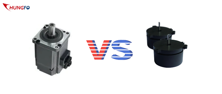
Choosing Between Direct Connected Spindle and Belt Type Spindle! This blog analyses core disparities. Performance and maintenance features are discussed.
As for the DCS and the BTS, the two come with their own pros. Find out which spindle is fit for you. Performance of your machine depends on this choice that you make. Stay tuned for comprehensive studies.
What Are the Core Differences Between Direct Connected and Belt Type Spindles?
· Operational Mechanisms
The direct connected spindle has a motor shaft connected directly to the spindle shaft.
This setup ensures minimal vibration. In a belt type spindle power transmission is achieved using a belt drive which is based on pulleys and belts.
Models with direct connection provide high precision with fewer moving parts. Belt type is a versatile option that comes with different pulley ratios. Both are suitable for specific applications in machining.
· Speed Control
The uniform speed of the spindles comes from the direct motor-shaft linkage. These spindles allow the machines to operate at high speed. The variable pulley diameters used in this type of spindles play an important role in speed adjustment, making them more flexible.
The speed stability of these systems is affected by the belt tension. Directly connected systems attain constant speeds flawlessly. The two spindles were intended to handle different machining.
· Torque Transmission
A straight connected countershaft transmits the torque right from the motor reducing power losses. These spindles ensure consistent torque. Belt spindles transmit torque through belts and pulleys, with a risk of slippage. Torque consistency can have issues of belt wear.
Direct connected systems make sure prompt torque transfer. Both have specific advantages depending on the application.
· Cost Efficiency
The issue with the direct connected spindles is that they are more expensive for their complicated design at first. Maintenance is usually less often. Belt type spindles are inexpensive to begin with, and their components are easier to change also.
These spindles might demand more frequent maintenance. Indirect systems are cheaper but less stable. Such devices regulate budgeting between performance and specific purposes.
How Do Direct Connected Spindles Enhance Machine Performance?
· Precision Levels
Precise direct connected spindles (DCS) decrease backlash to achieve higher levels of accuracy. They achieve ±0.001mm accuracy. The run out of BTS (belt type spindles) is greater than that of MLT. DCS employ high quality servo motors with rotational speed exceeding 10,000 rpm.
Pulley and belt are the resources the band BTS leverages. During DCS, the shaft alignment is made meticulously. BTS can experience misalignment.
An advanced feedback loop of the encoder is provided by DCS. Positioning BTS has limited accuracy. DCS systems mitigate thermal contraction and expansions effects. BTS belts, unfortunately, begin wearing out over time. The DCS ensures a better pose fix.
BTS introduces vibration. DCS provides improved repeatability. BTS requires frequent maintenance. A DCS is ideally for super precise jobs. BTS struggles with micro-movements. A DCS integrated system leads to repeatable machining results.
· Efficiency Boost
DCS, the direct connected spindles, make manufacturing process efficient in a way that the pin is closer to the ground. They use high-powered servo motors that are high in efficiency.
Spindles in Belt type (BTS) are susceptible to energy wastage through belts. DCS has direct power transmission which means that there is no signal loss from changes in voltage and current. BTS involves mechanical friction. DCS is functionally characterized by shorter response time.
BTS problem is caused by the mistimed torque transmission. DCS monitoring specifies constant rpm. BTS systems have tensions which are adjusted for some belts whereas for others tensions do not change.
DCS creates less maintenance outage, in contrast. BTS needs belt replacement on a regular basis since this part is constantly in contact with the wheel. DCS supports continuous operation.
BTS experiences slippage issues. DCS provides the most sophisticated cooling system. BTS has bad cooling performance. DCS maximizes power utilization. BTS operates less efficiently.
· Speed Variability
The direct resistance connected spindles (DRCS) have the advantage of speed variability. They are responsible for changing rpm dynamically. Belt type spindles (BTS) have small velocity ranges because of their design. DCS, on the other hand, employs VFD.
BTS works with transmission ratio fixed and the ratio is constant. DCS can regulate the rpm operation and the range is from low to high. The speed shifter in BTS will require manual attentiveness.
One virtue of DCS is its smoothness during the switching. The speed consistency is the major negative accompanying the BTS. DCS systems basically play a role in adaptive speed control.
Due to its mechanical limitation, BTS is subjected. DCS allows for quick generation speed changes, thus decreasing downtime associated with speed changes. It calls for several stopovers to rectify alignment.
ATC improves the accuracy between different cruise speeds. BTS lacks flexibility. The DCS is flexible enough to adjust to different raw material characteristics.
· Torque Consistency
The direct connected spindles called the Direct Connected Spindles (DCS) transmit torque output steadily. These robots feature servo-driven actuators with advanced precision.
Belt-type spindles (BTS) correspond with these torque fluctuations. DCS has constant torque throttle all through rpm range. At speeds over 80 miles per hour, the vehicle will encounter torque drops.
DCS better when it comes to the notion of load adjustment. Expansion of the belt is a direct influence on BTS. DCS systems include the feedback loops too.
There is a shortfall in the immediate generation control for BTS. DCS is declared accurate with respect to the torque. BTS structures have embedded slippage problems. DCS supports heavy-duty machining.
BTS is designed for maximum torque and acceleration. DCS minimizes mechanical wear. BTS system should be improved continually. The DCS eliminates the pulsing by providing the appropriate torque smooth delivery.
· Operational Stability
While direct connected spindles (DCS) create operation stability, they also guarantee grinding operations uninterrupted. They help to be anti-vibration, low in noise.
BTS type spindles (BTS) are vibration producing to the level of being dangerous. DCS is using the balanced structure motor. The ski lift mechanism in BTS is improperly designed, causing imbalances.
DCS provides consistent performance. DCS provides damper technology to avoid the negative effects of un-damped vibration modes. The BTS does not incorporate an advanced vibrational control mechanism. DCS enhances cutting quality. BTS compromises surface finish.
DCS supports high-speed machining. BTS limits operational speeds. DCS ensures long-term reliability. BTS has to exchange part instrumental frequently. DCS minimizes unplanned downtimes.
BTS involves more maintenance. DCS systems ensure the structural integrity of all affected structures.
Criteria
Direct Connected Spindles
Belt Type Spindles
Precision Levels
High precision (±0.001 mm)
Moderate precision (±0.01 mm)
Efficiency Boost
Higher efficiency (90%+)
Lower efficiency (70-80%)
Speed Variability
Wide range (500-40,000 RPM)
Limited range (500-10,000 RPM)
Torque Consistency
Consistent torque delivery
Variable torque
Operational Stability
High stability, less vibration
Moderate stability, more vibration
Table on How Do Direct Connected Spindles Enhance Machine Performance!
What Advantages Do Belt Type Spindles Offer in Industrial Settings?
· Cost Savings
The type of spindle with a belt (BTS) reduces initial investment costs. They have cheap pulleys systems. Higher motor costs are associated with the direct connected spindles.
BTS offers cost-effective maintenance. DCS requires expensive components. BTS has very basic mechanical parts. DCS requires the creation of tailor-made servo motors.
BTS systems decrease operating expenses. DCS increases maintenance costs. BTS offers a low cost alternative to erecting pylons and transmission lines. DCS employs expensive direct drive machines. BTS is the advantage of small manufacturers having low-cost.
· Flexibility Increase
Another advantage of Belt type spindles (BTS) is their versatility in speed control. They adjust the pulley size. Direct connected spindles (DCS) have predetermined speed ranges.
BTS allows easy accelerations. DCS needs complex programming. BTS systems became suitable for various machining operations. DCS lacks this flexibility.
BTS is particularly adaptable for processing a wide variety of materials. DCS is less adaptable. BTS enables easy customization. DCS has limited adjustability. BTS enhances operational versatility.
· Maintenance Ease
Belt-type spindles (BTS) develop ease of repair and maintenance. They replace the belts without any trouble. Spindles which are directly linked (DCS) have to use specially designed pieces of equipment. BTS systems require schedule disrupted as little as possible.
DCS involves complex repairs. BTS is designed for simple belt changes. DCS necessitates motor recalibrations. BTS components can be easily bought everywhere.
DCS parts are especially rare. BTS reduces service intervals. DCS demands frequent check-ups. BTS ensures straightforward troubleshooting.
· Environmental Suitability
BTS spindles operate well in severe conditions. They put up with dust and dirt. Direct connected spindles (DCS) require environment with lower discharges. BTS systems mediate temperature changes.
DCS experiences thermal variation problems. BTS uses the components that are resistant to mechanical stresses. DCS requires sensitive electronics.
BTS is reliable for industrial environments and networks. DCS suits controlled environments. BTS stands for avoiding interruptions in factory operation. DCS is more delicate. BTS makes the best of it in adverse conditions.
When Should You Choose a Direct Connected Spindle Over a Belt Type Spindle?
· High Precision
Where more precision is required, use direct connected spindles (DCS). DCS achieves ±0.001 mm accuracy. More run-out for the belt type spindles (BTS) is also observed. DCS uses high-resolution encoders. Lack of precise BTS systems limits its effectiveness.
DCS is capable of mitigating thermally induced shrinkage. BTS experiences thermal drift. DCS assembles the stable shaft alignment. Over time the angle of BTS will deviate. DCS ensures consistent accuracy. BTS struggles with micro-movements. DCS boasts on high precision tasks.
· Enhanced Durability
Choose DCS for excellent durability. DCS is equipped with the servo motors of the highest performance. Belt drive spindles (BDS) are belted and hence risky. DCS components are in accordance with the high loads. BTS parts wear quickly. DCS offers advanced cooling systems.
BTS heat is not efficiently controlled. The DCS systems require low maintenance. BTS involves belt replacement frequently. DCS ensures long-term reliability. BTS involves regular servicing. DCS provides superior longevity. BTS components degrade faster.
· Optimal Speed
Opt for DCS option for highest speed attainment. DCS incorporates the use of variable-frequency drives. Fixed pulleys create spindles with belt type (BTS). DCS provides a modified curve of rpm settings.
BTS offers various manual speed adjustments. CNC systems, however, are capable of high-speed machining. BTS still has the bottleneck problem.
DCS provides rapid acceleration. BTS experiences unavoidable speed transition sluggishness. DCS ensures a steady speed during drifts. BTS cars have speed irregularities. DCS enhances machining efficiency.
· Superior Torque
Selecting direct drive spindles (DCS) will provide the highest torque. DCS is characterized by providing constant torsion. Belt type spindles (BTS) are torque-variation sensitive. DCS facilitates constant torque throughout the rpm range. The far torque of BTS is attenuated when speed is higher.
DCS uses precision-engineered motors. BTS is subject to the pulling strength. DCS supports heavy-duty machining. BTS faces the problem of relative high-torque.
The DCS control systems use real time torque control. BTS lacks such precision. DCS delivers careful linear torque. BTS experiences slippage.
· Critical Applications
In regard to critical functions, opt for direct connected spindles (DCS). DCS ensures precise performance. The belt-type spindles (BTS) are not dependable. DCS supports high-precision tasks.
BTS struggles with accuracy. DCS maintains stable operation. BTS experiences frequent misalignment. DCS systems have more elaborate feedback cycles. BTS lacks real-time monitoring.
DCS is particularly notable in critical surroundings. BTS falters under stress. DCS provides consistent results. BTS requires constant adjustments. Exactness is a DCS benefit while being used for crucial machining.
Criteria
Direct Connected Spindles
Belt Type Spindles
High Precision
Required (±0.001 mm)
Not critical (±0.01 mm)
Enhanced Durability
Long lifespan, low maintenance
Shorter lifespan, higher maintenance
Optimal Speed
Necessary for high-speed operations
Sufficient for lower speed needs
Superior Torque
Essential for heavy-duty tasks
Acceptable for light tasks
Table on When Should You Choose a Direct Connected Spindle Over a Belt Type Spindle!
What Are the Maintenance Implications for Each Type of Spindle?
· Routine Checks
Directly connected spindles (DCS) are always thoroughly visually examined. Such procedures include motor inspection and encoder calibration. The belt type spindles (BTS) require for belt tightening. DCS systems require sensor alignment to be operated regularly. In BTS, pulley wears need to be inspected.
DCS check-ups relates to thermal management. BTS inspection is to ensure the belt is not damaged. DCS requires vibration monitoring. BTS needs to be frequently replaced as the belt wears out.
DCS makes use of modern diagnostics. BTS prefers faster checking techniques. DCS ensures long-term accuracy.
· Lubrication Needs
Spindles connected via direct current (DCS) have very few lubrication requirements. They use sealed bearings. Belt-type spindles (BTS) require periodic belt lubrication. DCS systems utilize auto lubricating parts. BTS requires periodic oiling. DCS operates with an advanced grease removal system.
BTS demands manual lubrication. DCS enhances the grease life performance. BTS lubrication significantly impacts belt life. DCS uses high-efficiency lubricants.
BTS employs standard oils. DCS reduces maintenance intervals. BTS requires regular inspection of its lubrication.
· Component Wear
Direct connected spindles (DCS) do not wear out components easily. They use precision-engineered parts. Belt type spindles (BTS) are a common cause of belt wear.
DCS systems contain rugged bearings. The BTS incorporates the replacement belts. DCS lowers wear down by means of the direct drive system. BTS has disadvantage of belt stretch.
DCS is made of hardened steel shafts. BTS uses rubber belts. DCS reduces maintenance costs. BTS usually entails frequent parts replacing. DCS contributes to longer part life.
· Operational Lifespan
Unlike other connected spindles, direct connected spindles (DCS) have a longer usable lifespan. They are servo motor-based. Belt type spindles (BTS) have shorter lifetimes.
DCS systems use resistant components. BTS parts wear quickly. DCS is thus superior to the traditional convection ovens since it is more efficient in thermal management.
BTS lacks efficient cooling. DCS stays performance over the time. BTS experiences gradual degradation. DCS need a lesser number of repairs. BTS involves regular maintenance. DCS offers consistent operation.
Conclusion
Selecting between Direct Connected Spindle and Belt Type Spindle! We discussed the issues of accuracy, quickness, and long-term survival. DCS ensures accuracy and durability that other devices do not. BTS can help to cut cost and increase flexibility. Maintenance needs vary significantly.
Each spindle type has tailored specific benefits. Your choice affects the general quality of the machine's performance. Consider all factors carefully. Visit CNCYANGSEN for expert advice. Choose your spindle right by today!
FAQs!
Q: Why Should You Choose Direct Connected Spindle For High-Precision Tasks?
A: Direct Connected Spindles (DCS) has an outstanding performance in accuracy and error is controlled within ±0.001mm precision. They prevent cold chilling and thermal expansion, resulting into high level of accuracy thus making them suitable for every precision machining job.
Q: How Does Maintenance Differ Between Direct Connected Spindle And Belt Type Spindle?
A: Direct-connected spindles (DCS) have an advanced diagnostic system that does not need an express maintenance. Belt-type spindle (BTS) requires a more frequent upkeep which includes regular belt replacement and lubrication.
Q: Which Spindle Type Offers Better Durability In Harsh Environments?
A: DCS operates very well in terms of the toughness thanks to the utilization of advanced materials and sealing bearings. The belt type spindles (BTS) maintain high efficiency but due to belt wear constraints, their operating life is relatively short.
Q: How Do Operational Loads Affect Direct Connected Spindle And Belt Type Spindle?
A: In direct connected spindles (DCS) high-torque servo motors are capable of processing dynamic loads with uniform torque. Silent or Hi-torque spindles (BTS) are not effective under high loads and vary most.
Are you looking to increase your production capabilities and stay ahead of the competition? Computer Numerical Control (CNC) technology is something you should surely opt for. According to the National Institute of Standards and Technology (NIST), CNC technology increases production efficiency by up to 85%, making it a pivotal force in modern manufacturing. Specifically, it has brought better parts and high accuracy to the manufacturing floor, including the use of CNC lathes. The present article focuses on the advantages of the CNC lathe machine, how its use enhances production, and how one can compare vertical and horizontal CNC lathes.
We will also learn how CNC technology improves the machining process and help you identify the suitable lathe machine for your business.
What is the Basic Principle of a CNC Lathe Machine?
CNC lathe is a machinery developed to perform cutting, boring, and turning operations on materials with high precision and speed. As opposed to conventional techniques, CNC lathes incorporate specific computational ascetics to regulate numerous factors of the matter. This cuts down on the involvement of human intervention, which may lead to the making of errors and hence enhances the accuracy of the machining done.
CNC lathe machines are basically used to hold the workpiece against a turning tool, which rotates the workpiece while cutting, drilling, and threading at the same time. CNC lathe machines are available in either vertical or horizontal configurations, depending on the requirements for the particular task at hand, and each has its unique strengths.
Vertical vs. Horizontal CNC Lathe: Selecting the Best Lathe Machine
Vertical CNC Lathes:
Instructions
Typical Values
Working
Spindle Speed Range (RPM)
20 - 3,500 RPM
Suitable for large workpieces, slower due to part size.
Maximum Cutting Speed (m/min)
150 - 400 m/min
Provides good cutting efficiency for more significant components.
Spindle Motor Power (kW)
22 - 55 kW
Higher power supports heavy-duty operations.
Maximum Workpiece Diameter (mm)
1,500 - 3,000 mm
Designed for more extensive, heavy workpieces like gear blanks.
Maximum Workpiece Weight (kg)
5,000 - 15,000 kg
Supports heavier parts due to vertical structure.
Axis Travel (Z-axis)
1,000 - 2,000 mm
Vertical travel supports deep drilling.
Tool Turret Speed (Tool Change Time)
0.5 - 2.5 sec
Efficient tool change improves machining cycles.
Surface Roughness
1.6 - 3.2 µm
Good surface finish for large-diameter parts.
A CNC lathe machine is a sophisticated piece of equipment meant to help execute turning, boring, and cutting of different materials in an exact manner. Another significant difference is that the CNC lathes do not use manual controls as do the conventional ones. Instead, they feature computer systems that interface to control several parameters of the machining procedure.
The primary use of a CNC lathe is to turn a piece of material against a center with a cutting tool, which cuts, bends, or drills the required shape accordingly. CNC lathe machines can be vertical or horizontal according to the working requirements; every structure has suitable machining applications.
Horizontal CNC Lathes:
Specifications
Typical Values
Working
Spindle Speed Range (RPM)
50 - 6,000 RPM
Higher speeds for cylindrical parts and small workpieces.
Maximum Cutting Speed (m/min)
250 - 600 m/min
Higher cutting speeds for mass production.
Spindle Motor Power (kW)
18 - 45 kW
Suitable for medium to high production demands.
Maximum Workpiece Diameter (mm)
400 - 800 mm
Designed for smaller, high-speed production parts.
Maximum Workpiece Weight (kg)
500 - 3,000 kg
For lighter, high-precision components like shafts.
Axis Travel (Z-axis)
700 - 1,200 mm
Horizontal travel for elongated parts like rods
Tool Turret Speed (Tool Change Time)
0.2 - 1.5 sec
Faster tool changes for higher throughput.
Surface Roughness
0.8 - 1.6 µm
Excellent surface finish for precision components.
The horizontal CNC lathe employs features like precision marble beds and hydro-static spindles, and it is lightweight with particle damping to achieve high accuracy. These characteristics help to improve dynamic performance in that; there is a reduction in the vibration level and a higher natural frequency hence; desirable machining performance.
Specialized Horizontal CNC Lathes
Some of the specialized horizontal CNC lathes include automobile steering bars with machining fixtures, whereby specific spindle boxes support the design, hence minimizing labor. These lathes have horizontally positioned spindles, which makes them suitable for turning long cylindrical products like shafts. They are also suitable for mass production due to their stiffness in use, high cutting speeds, and easy chip removal.
Choosing Between Vertical and Horizontal Lathes:
The type of CNC lathe used, vertical or horizontal, depends on the dimensions of the workpiece, its difficulty level, and the batch production required. Vertical CNC lathes are unique for rigid, large, or complex workpieces due to their high torque and compact structure, although some machines may vibrate.
However, horizontal CNC lathes provide better accuracy and faster cutting to improve the production of low-cross-sectional, cylindrical goods. While the vertical lathe is designed for specific use in areas such as automotive, the horizontal lathe is widely used in almost all fields.
How Do CNC Lathes Enhance Precision and Efficiency?
1. Lightweight CNC Lathes and Vibration Control for Precision Manufacturing
CNC Lathes with new lightweight construction and Particle Damper Technology allow excellent performance and lower vibration. They decrease their weight by up to 50 pounds as much as possible. 8% makes them more efficient in high-speed productions without compromising accuracy. This enhanced mode of vibration control enhances the finishing of the surface and durability of tools, which is essential in industries such as aerospace and automobile. This is appreciable in vertical and horizontal CNC lathes, making the operations smooth and efficient.
2. Enhanced Machining Accuracy and Faster Setup with CNC Programming
Computer numerical controlled programming helps to guarantee high Machining accuracy to minimize tool path deviations that may cause errors in the parts. Such accuracy is crucial within industries such as aerospace and automotive, where part and component dimensions are significantly regulated. However, the setup times are also reduced with the CNC lathes since they can be quickly reprogrammed, and hence, the lathe's productivity is superior to that of conventional machines.
3. Multifunctionality and Hybrid CNC Machines for Versatility
Many different operations, such as turning, thread cutting, drilling, etc, are possible with attachments on a CNC lathe. Turning & milling hybrid CNC machines compile both turning and milling operations in a single setup and provide a broader range of geometries than conventional turning systems. It also increases flexibility and performance in aerospace, metalworking, and automotive fields.
4. Automation and Optimized Cutting Speeds for Production Efficiency
Automation of CNC lathe machines reduces manual interferences and decreases errors as the machines work accurately. Higher cutting speeds that are achieved and regulated according to mechanical properties improve the cycle time and longevity of the cutting tools. This, coupled with automation and optimized speeds, makes manufacturing operations more efficient, controls the cost of labor, and makes manufacturers more competent.
5. Precision Manufacturing and Vibration Control for Quality Parts
CNC lathes provide greater accuracy in dimensions, which is paramount in manufacturing medical equipment and aircraft, among others. Proper control of vibrations helps to have even surfaces and makes tools last long. Since it has integrated control for the tension of the belt used in the CNC lathes, the machining is steady, and there is no uneven production of parts of low quality, hence minimizing wastage.
What are the Applications of CNC Lathe Technology?
1. Machine Shop Programming
Turret-type CNC lathes are especially useful for many machine shop computer programming applications. They are proficient in chucking and bar processing, enabling various machining. These skills are beneficial when handling several setups with a lot of delicacy, making them very useful in machine shops. CNC lathe technology increases production by automating time-consuming processes, hence crucial in industries requiring high precision.
2. Additional Attachments and Versatile Operations
Components like grinding spindles to CNC lathes can introduce a new level of functional versatility. This enables a CNC lathe to attain and grind operations within a single setting. Such attachments must be run with the assistance of high-level software to manage the grinding wheel's operation. Such versatility enables the CNC lathes to perform various machining requirements while proving the versatility of modern CNC technology.
3. Surface Roughness Control and High Precision
New methods in CNC lathe technology, such as artificial neural networks (ANN), determine surface roughness. Satisfactory surface finishes and the dimensional accuracy required for the workpiece can, therefore, be realized through optimization of cutting parameters using predictive models on CNC lathes. This high precision is essential in sectors where the flatness of the surface and dimensions are crucial factors. From applying ANN to CNC lathes, this paper also demonstrates how the technology improves machining steadiness and output quality.
4. Educational Models and Accessibility
Developing affordable CNC wood lathes is one of the viable ways ITTN can spread the use of CNC technology, especially in learning institutions. These models can significantly minimize the cost of production and occupation space and serve as a helpful learning apparatus for students and hobbyists. Due to new light and cheap designs, the educational institution can provide practical experience with CNC lathes and acquire a better understanding of precise machining and automation.
5. Lightweight Designs and CAM Integration
Lightweight designs, including integrating linear motors in CNC lathes, enable sub-micron positioning accuracy. An increase in speed precision increases high-speed operation and also overall machining performance. Also, Computer Aided Manufacturing (CAM), when implemented along with the CNC lathes, optimizes the programming processes and enhances the performance by achieving better accuracy in the machining process and part fabrication. The advancements in CNC lathe technology prove the role of the technology in producing optimal results in manufacturing.
What are the Benefits of CNC Lathe Machines for Manufacturing?
1. Improved Machining Precision and Higher Productivity
CNC lathes are precision machines that provide accurate machinery or operations, usually demanded by the aerospace and automotive industries. ORIZATION ensures that every part of the product is machined to a required level of accuracy minus human interference. In the same respect, CNC lathes do not undergo regular downtimes; hence, they can work for long and produce high volumes in equal measure. In this method, several parts can be machined simultaneously, increasing efficiency.
2. Multipurpose Use in Machining Processes and Labour Savings
CNC lathes are flexible; they can cut, drill, thread, and perform boring operations on this lathe type. This means that they can be used for a small number of workers, as those found in a small workshop, and for a relatively large number of workers, as may be found in manufacturing industries. Furthermore, automation in CNC lathes lowers the demand for skilled personnel as almost all operations are carried out by the machine. This reduces the expenses on employees while at the same time ensuring an organization retains or improves the quality of its productions.
3. Consistency, Repeatability, and Increased Efficiency
Traditional lathes take substantial time to produce numerous similar parts with high accuracy and consistency. In contrast, CNC lathes give consistency, allowing one to get a thousand similar parts without much deviation. This is important in industries where product standardization is necessary, especially throughout large batch production. The positive performance of CNC lathes makes it easier to improve productivity and meet high-quality demands, making them crucial components of modern output.
What are some of the Best CNC Lathe Machines for Manufacturers?
1. HAAS Automation
Based in the United States of America, HAAS Automation is a reputable CNC lathe machine producer that produces highly durable and accurate lathes suited for different sectors. It is made to offer CNC machining solutions to companies, enabling enhanced efficiency in the lathe machines primarily used in complicated exercises. Due to this flexibility, HAAS Automation’s horizontal and vertical CNC lathes provide a solution for aerospace and automotive industries with their needs for precision and performance.
2. DMG Mori
It is well-established for manufacturing several flexible CNC lathe machines with the latest CNC technology for lathe machines. Its vertical and horizontal CNC lathes tackle high-speed machining and have many advantages in lathe manufacturing. These machines are particularly advantageous in organizations that have a standard need for devices that are presumed to perform at exceptionally high levels of capacity while at the same time being versatile; therefore, the reason why companies seeking to enhance their precision machining needs go for these machines.
3. Okuma
Okuma’s CNC lathe machines also have the highest level of precision, making them suitable for precision manufacturing. They provide technology that enhances manufacturing operations, such as automated CNC programming. Okuma’s machines are commonly used in aerospace and automotive industries, where machining and lathe machines are essential in manufacturing high-quality parts with small tolerances.
How does CNC Lathe Technology Boost Productivity?
1. Automation and Minimizing Human Error
CNC lathe technology optimizes workpiece control and tooling while improving repeatability. This reduces or minimizes reliance on human operators, making CNC lathe machines more accurate and efficient. Since the CNC lathe initiates the operation, human error is eliminated, resulting in a high-quality finish, as required in precision machining industries.
2. High Precision, Consistency, and Improved Machining Stability
CNC lathes are precision machines capable of providing repeatability, crucial in producing components with complicated shapes and close tolerances. Sores and numerical controls are also regulated with servo control systems in state-of-the-art CNC lathe machines to improve machining stability. This makes the CNC lathe machines vital for accurate machining and lathe machine effectiveness in manufacturing.
3. Increased Efficiency and Faster Production Cycles
Efficiency is another significant benefit of implementing lean manufacturing since it enables the production of larger goods in a shorter time.
CNC lathes have improved production by reducing the time spent setting up and actual output. Because they can easily alternate between tasks and maximize cutting speeds, they complete production more often and faster. This increases the overall efficiency of lathe production and reduces wastage, making CNC lathe machines suitable for large-scale production.
4. Versatile Operations and Time Savings
The CNC lathes’ flexibility is rightly justified because it can perform turning, drilling, and threading operations through various attachments. These benefits include integrating several functions into a single machine and reducing the time required to employ several machines. Usability in a way that allows for multiple operations in one setting makes CNC lathe machines more efficient in a range of manufacturing operations.
5. Cost Reduction and Operational Efficiency
CNC lathe machines cut costs by using one machine to perform multiple operations, reducing the production cost. Improved operating efficiency is obtained through better machine time balance and a lesser need for manual intervention. These changes make the CNC lathes indispensable for modern manufacturing, increasing productivity and competitiveness while reducing operational costs.