1. First, consider the processing order of parts. Drill first and then flatten (this is to prevent shrinkage during drilling); Rough turning first, then fine turning (this is to ensure the accuracy of parts); Process large tolerances first and then small tolerances last (this is to ensure that the surface of small tolerance dimensions is not scratched and prevent parts from deformation).
2. Then according to the hardness of the material, we choose a reasonable speed, feed rate and cutting depth. Carbon steel materials choose high speed, high feed rate and large cutting depth. For example: 1Gr11, choose S1600, F0.2, cutting depth 2mm; cemented carbide chooses low speed, low feed rate and small cutting depth. For example: GH4033, choose S800, F0.08, cutting depth 0.5mm; titanium alloy chooses low speed, high feed rate and small cutting depth. For example: Ti6, choose S400, F0.2, cutting depth 0.3mm. Take the processing of a certain part as an example: the material is K414, which is a special hard material. After many tests, S360, F0.1, and cutting depth of 0.2 were finally selected to process qualified parts.
Tool Setting Skills:
Tool setting is divided into tool setting instrument tool setting and direct tool setting. Some lathes in my previous work did not have tool setting instruments, so they were directly set. The tool setting skills mentioned below are direct tool setting. First, select the center of the right end face of the part as the tool setting point and set it as the zero point. After the machine tool returns to the origin, each tool that needs to be used is set with the center of the right end face of the part as the zero point; when the tool touches the right end face, enter Z0 and click Measure, and the tool compensation value of the tool will automatically record the measured value, which means that the Z-axis tool setting is done. The X-axis tool setting is a trial cutting tool setting. Use the tool to turn the outer circle of the part less. Measure the outer circle value (such as x is 20mm) and enter x20. Click Measure, and the tool compensation value will automatically record the measured value. At this time, the X-axis is also well set.
This tool setting method will not change the tool setting value after the machine tool is powered off and restarted. It can be used for mass production of the same part for a long time. There is no need to re-set the tool even if the lathe is turned off during the process.
Debugging skills.
Complete the Processing of Parts:
After the first trial cutting of the parts is completed, they will be produced in batches, but the qualification of the first piece does not mean that the whole batch of parts will be qualified, because in the process of processing, the tool will be worn due to the different processing materials. The processing material is soft, the tool wear is small, and the processing material is hard, the tool wear is fast. Therefore, during the processing, it is necessary to measure and check frequently, increase and decrease the tool compensation value in time to ensure the qualification of the parts.[Take the previously processed parts as an example: the processing material is K414, the total processing length is 180mm, because the material is very hard, the tool wears very quickly during processing, from the starting point to the end point, there will be a 10~20mm slight deviation due to tool wear, so it is necessary to add a 10~20mm slight deviation in the program manually, so as to ensure the qualification of the parts.
In short, the basic principle of processing: first rough processing, remove the excess material of the workpiece, and then fine processing; vibration should be avoided during processing; avoid thermal denaturation of the workpiece during processing. There are many reasons for the vibration, which may be excessive load; it may be the resonance of the machine tool and the workpiece, or it may be the lack of rigidity of the machine tool, or it may be caused by the passivation of the tool. The following methods can be used to reduce vibration; reduce the lateral feed rate and processing depth, check whether the workpiece is clamped firmly, increase the speed of the tool or reduce the speed to reduce resonance, and check whether it is necessary to replace the new tool.
Prevent Machine Tool Collision:
Machine tool collision is a great damage to the accuracy of the machine tool, and the impact on different types of machine tools is different. Generally speaking, it has a greater impact on machine tools with weak rigidity. Therefore, for high-precision CNC lathes, collisions must be absolutely eliminated. As long as the operator is careful and masters certain anti-collision methods, collisions can be completely prevented and avoided.
The main reasons for collisions are:
First, the diameter and length of the tool are entered incorrectly;
Second, the size of the workpiece and other related geometric dimensions are entered incorrectly, and the initial position of the workpiece is incorrectly positioned;
Third, the workpiece coordinate system of the machine tool is set incorrectly, or the machine tool zero point is reset during the processing process, resulting in changes. Machine tool collisions mostly occur during the rapid movement of the machine tool. The harm of collisions at this time is also the greatest and should be absolutely avoided. Therefore, the operator should pay special attention to the initial stage of the machine tool in the execution of the program and when the machine tool is changing the tool. At this time, once the program is edited incorrectly, the diameter and length of the tool are entered incorrectly, then it is easy to collide. At the end of the program, the sequence of the tool retraction action of the CNC axis is wrong, then a collision may also occur.
In order to avoid the above collisions, the operator should give full play to the functions of the five senses when operating the machine tool. Observe whether the machine tool has abnormal movements, sparks, noise and abnormal sounds, vibrations, and burning smells. If an abnormal situation is found, the program should be stopped immediately, and the machine tool can continue to work after the machine tool problem is solved. In short, mastering the operation skills of CNC machine tools is a gradual process and cannot be achieved overnight. It is based on mastering the basic operation of machine tools, basic mechanical processing knowledge and basic programming knowledge. The operation skills of CNC machine tools are not static. It requires the operator to give full play to the organic combination of imagination and hands-on ability, and is innovative labor.
Modern manufacturing faces increasing demands for precision, efficiency, and the ability to handle intricate designs. Conventional machining methods often struggle to produce the complex components required in the aerospace, automotive, and medical industries.
5-axis bridge mills offer an advanced solution, addressing these challenges by enabling multidirectional cutting, reducing setups, and ensuring unparalleled accuracy. This technology not only simplifies complex machining but also improves production efficiency and consistency, meeting the evolving needs of industries.
Manufacturers achieve superior performance by integrating 5-axis machining capabilities with the robust structure of bridge mills. The combination allows for precise handling of large workpieces, ensuring high-quality results even in demanding applications. This guide explores the capabilities and benefits of 5-axis bridge mills in depth.
Understanding 5-Axis Machining
The 5 Axis Explained
In 5-axis machining, the term “axes” refers to the direction the cutting tool moves. The X, Y, and Z axes represent linear movements: left to right, forward to backward, and up and down, respectively. The A and B axes enable rotational movements, allowing the tool to tilt and turn for enhanced flexibility.
These five axes work together to maneuver the cutting tool around apart with precision. This capability is especially useful for machining complex shapes, as it allows cutting from multiple angles without repositioning the workpiece. The seamless movement across all axes minimizes errors and improves surface quality.
How 5-Axis Movements Enhance Machining
The ability to move along five axes ensures access to hard-to-reach areas of intricate components. This reduces the need for multiple setups, saving time and improving consistency. By positioning the tool optimally at every process stage, the machine can cut more accurately.
Rotational movements also allow shorter tools, reducing vibrations and enhancing precision. By enabling smoother and more efficient cutting paths, 5-axis movements ensure that even complex geometries are machined accurately and efficiently.
Key Capabilities of 5 Axis Technology
One of the primary advantages of 5-axis technology is its ability to perform multidirectional machining. This capability is essential for creating intricate geometries, such as curved surfaces and deep cavities, in a single setup. The reduction in manual intervention further ensures uniformity across parts.
In addition to handling complex designs, 5-axis machining offers precision and efficiency. The technology delivers high accuracy by minimizing alignment errors and reducing the required operations. This makes it ideal for industries requiring detailed and consistent results, such as aerospace and medical device manufacturing.
Key Components of 5 Axis Bridge Mills
Bridge Structure
The bridge structure in 5-axis bridge mills is designed to ensure stability during machining. It is typically made from rigid materials like cast iron or steel, which reduce vibrations and maintain precision. The design focuses on evenly distributing weight across the structure to support large, heavy workpieces without compromising accuracy.
A well-engineered bridge structure enhances the machine's ability to perform high-precision operations. Its robust construction minimizes deflection and ensures consistent results, even when handling complex or lengthy machining tasks.
Spindle Technology
Spindles are central to the performance of 5-axis bridge mills, with high-speed and torque-driven types being the most common. High-speed spindles are used for lightweight materials and detailed cuts, while torque-driven spindles excel in machining harder materials.
The power of the spindle directly influences the machine's capability. A powerful spindle ensures smooth and efficient cutting, even at high feed rates, making spindle selection a critical factor in optimizing performance for specific machining tasks.
Control Systems
Modern 5-axis bridge mills rely on advanced CNC technology for simultaneous multi-axis operation. These systems enable the coordination of linear and rotational movements, allowing precise and complex machining in a single setup.
Software integration plays a key role in enhancing precision. Advanced software programs assist in toolpath optimization and error reduction, ensuring that the machine operates at peak efficiency. Control systems also support user-friendly interfaces for easier programming and operation.
Worktables
Worktables in bridge mills are available in fixed and moving configurations. Fixed tables offer stability for heavy workpieces and ensure precise machining without movement. Moving worktables, on the other hand, improve flexibility and are ideal for smaller, dynamic parts.
The choice of worktable impacts machining efficiency. Fixed tables are better for operations requiring maximum accuracy while moving tables reduce setup times for intricate tasks. Proper selection ensures that the machine meets the specific requirements of diverse applications.
Comparing 5 Axis Bridge Mills with Other Machines
5 Axis Bridge Mills vs. 3 Axis Bridge Mills
The main difference between 5-axis and 3-axis bridge mills is their movement capabilities. While 3-axis machines operate along the X, Y, and Z axes, 5-axis bridge mills include rotational movements, allowing the tool to tilt and turn. This enables the machining of more intricate geometries in fewer setups.
Applications also differ significantly. 3-axis machines are ideal for simpler designs and basic cuts, while 5-axis bridge mills handle complex components such as turbine blades and aerospace parts. Reaching hard-to-access areas without repositioning makes 5-axis machines more versatile for advanced manufacturing needs.
5 Axis Bridge Mills vs. 5 Axis Gantry Machines
Both 5-axis bridge mills and gantry machines can do multi-axis machining but serve different purposes. Due to their rigid structure, bridge mills excel at handling heavier and larger workpieces, making them suitable for industries like heavy equipment manufacturing.
Gantry machines, on the other hand, offer more flexibility for oversized parts that require broader coverage. When precision and stability are top priorities, especially for small to medium-sized components, bridge mills are preferred. They also provide better accessibility to workpieces for detailed operations.
Advantages Of Horizontal and Vertical Machining Centers
5-axis bridge mills offer superior scalability and precision compared to horizontal and vertical machining centers. Their robust structure allows them to accommodate larger, heavier workpieces without sacrificing accuracy.
Bridge mills also reduce the need for multiple setups, a limitation often found in traditional machining centers. This not only saves time but also enhances consistency across parts. Additionally, the combination of linear and rotational movements provides unmatched versatility, enabling the efficient production of complex geometries.
Key Benefits of 5 Axis Bridge Mills
Precision and Accuracy
5-axis bridge mills enable single-setup machining, significantly reducing errors that occur during repositioning. The ability to machine a component from multiple angles in one go ensures consistent precision. This is especially beneficial for intricate parts requiring tight tolerances, such as aerospace or medical components.
Accurate tool positioning across all five axes contributes to maintaining high-quality standards. The reduced risk of misalignment minimizes waste, making 5-axis bridge mills a reliable choice for precision manufacturing.
Time and Cost Efficiency
The advanced design of 5-axis bridge mills eliminates the need for frequent workpiece repositioning. This saves considerable time and speeds up production cycles, allowing manufacturers to meet tight deadlines.
With fewer setups required, labor costs are also reduced. The increased productivity ensures more components are produced in less time, improving overall operational efficiency.
Material Versatility
One of the standout features of 5-axis bridge mills is their ability to handle a wide range of materials. These machines are versatile enough to meet diverse industrial needs, from metals like steel and aluminum to composites and plastics.
This adaptability makes them suitable for various industries, including automotive, aerospace, and medical sectors. The capability to switch between materials without compromising performance ensures broader application possibilities.
Improved Surface Finishes
5-axis bridge mills are equipped to produce superior surface finishes, even on intricate or curved parts. The ability to approach a component from optimal angles reduces tool marks and ensures smooth results.
This advantage is critical for industries that require high-performance parts with flawless finishes, such as turbines or precision molds. The advanced cutting paths supported by 5-axis technology contribute to achieving consistent surface quality, enhancing the functionality and aesthetics of the final product.
Applications of 5 Axis Bridge Mills
Aerospace
The aerospace industry relies heavily on 5-axis bridge mills for manufacturing complex and precise components. These machines create turbine blades requiring intricate geometries to optimize aerodynamic performance. Structural components and engine parts, often made from high-strength materials, are also efficiently machined using 5-axis technology.
5-axis bridge mills ensure consistency and accuracy in aerospace manufacturing by reducing the need for multiple setups. This capability helps meet the industry's strict standards for safety and performance.
Automotive
In the automotive sector, 5-axis bridge mills create high-precision molds, dies, and engine blocks. These machines enable the production of detailed components that play a critical role in vehicle assembly and operation.
The ability to handle diverse materials, including lightweight alloys, makes 5-axis technology suitable for modern automotive design. This versatility allows manufacturers to meet demands for improved vehicle performance and fuel efficiency.
Medical
The medical industry benefits from 5-axis bridge mills for machining components like prosthetics, surgical tools, and dental implants. These machines provide the accuracy to create parts that meet strict dimensional tolerances.
For prosthetics and implants, 5-axis machining ensures a customized fit and smooth surface finish, improving patient outcomes. The precision these machines offer in surgical tools enhances functionality and reliability during medical procedures.
Energy
In the energy sector, 5-axis bridge mills are widely used to produce components for renewable energy systems and turbines. These include parts for wind turbines, hydroelectric systems, and other sustainable energy technologies.
The machines' ability to process hard-to-machine materials, such as stainless steel and titanium, is essential for energy applications. This ensures durability and performance in harsh operational environments. Additionally, the flexibility of 5-axis bridge mills supports the creation of innovative designs for energy-efficient systems.
Key Considerations for Choosing a 5-Axis Bridge Mill
Workpiece Size and Complexity
The size and complexity of the workpiece are crucial factors when selecting a 5-axis bridge mill. Machines should be evaluated for their ability to handle specific project requirements, including large or intricate components. Choosing the right size ensures efficient operations without compromising precision.
Material Handling Capabilities
Compatibility with the materials used in manufacturing is essential. Depending on the application, the machine should support various materials, such as metals, composites, or plastics. Ensuring proper material handling capabilities enhances efficiency and reduces the risk of machine wear.
Software and Automation
Advanced CAD/CAM integrations are vital for maximizing the machine’s potential. These systems allow for precise toolpath creation and streamlined workflows. Automation features, such as automatic tool changers, enhance productivity by minimizing manual intervention.
Cost vs. Long-Term Value
The initial cost of a 5-axis bridge mill must be weighed against its long-term value. Manufacturers should consider the return on investment (ROI) based on production volume, reduced labor costs, and improved output quality. A well-chosen machine offers significant benefits over time.
Innovations and Future Trends
Advancements in 5 Axis Bridge Mill Technology
Modern 5-axis bridge mills are incorporating adaptive machining technologies and AI-driven optimizations. These innovations enable real-time adjustments during operations, improving precision and reducing errors. AI integration also enhances process efficiency by analyzing data and optimizing machining paths for complex components.
Sustainability in Machining
Sustainability is becoming a key focus in the machining industry. Energy-efficient designs in 5-axis bridge mills reduce power consumption while maintaining high performance. Additionally, eco-friendly materials and waste-minimization techniques align with global efforts to make manufacturing more sustainable.
Potential Future Applications
The role of 5-axis bridge mills is set to expand with advancements in automation and Industry 4.0 technologies. Enhanced connectivity and intelligent systems will enable seamless integration with automated production lines. This evolution will make these machines even more essential for high-precision, large-scale manufacturing in aerospace, automotive, and renewable energy industries.
Maintenance and Operational Tips
Routine Maintenance Practices
Routine maintenance is essential for ensuring the longevity and performance of 5-axis bridge mills. Regularly inspecting and cleaning components such as spindles, worktables, and guides can prevent wear and tear. Lubricating moving parts and monitoring coolant levels are also crucial for smooth operations and reducing downtime.
Troubleshooting Common Issues
Operators should be prepared to address common issues such as tool misalignment or software glitches. Checking the calibration of axes and ensuring proper tool placement can resolve many problems. In cases of irregular machine behavior, consulting the machine's diagnostics and manuals can help identify and fix underlying causes.
Operator Training and Expertise
Skilled operators play a vital role in optimizing the performance of 5-axis bridge mills. Training programs should focus on developing machine setup, programming, and troubleshooting expertise. Familiarity with advanced software and control systems ensures operators can maximize the machine’s capabilities while minimizing errors.
Conclusion
5-axis bridge mills are a reliable investment for industries requiring precision, efficiency, and versatility in machining. Their ability to handle complex geometries, diverse materials, and large workpieces makes them essential for the aerospace, automotive, and medical sectors. By integrating advanced technology and automation, these machines enhance productivity while ensuring consistent quality. With reduced production time and minimized errors, 5-axis bridge mills offer long-term value and a future-ready solution for modern manufacturing needs.
Computer Numerical Control (CNC) machining is a manufacturing process that employs computerized controls and machine tools to remove layers of material from a workpiece, producing custom-designed parts. This technology is essential for manufacturing high-precision and complex components across various industries. CNC machining offers advantages such as high precision, repeatability, and the ability to produce complex geometries.
CNC machines operate through pre-programmed software and code that controls the movement of production equipment. This automation allows for the high-precision creation of parts and components that meet exacting specifications. The primary types of CNC machines include mills, lathes, and routers, each suitable for different types of machining tasks.
Key Products Offered
At CNC Yangsen, we specialize in the production of high-quality CNC machined parts. Our product range includes:
· CNC Machined Aluminum Parts: Lightweight, durable, and corrosion-resistant parts used in aerospace, automotive, and electronics.
· CNC Machined Steel Parts: Strong and wear-resistant components ideal for heavy machinery and industrial applications.
· CNC Machined Plastic Parts: Lightweight and versatile parts used in medical devices, consumer electronics, and automotive interiors.
· CNC Prototyping Services: Rapid production of prototypes to test designs before mass production.
CNC Machined Aluminum Parts
Aluminum is a popular material in CNC machining due to its excellent machinability, strength-to-weight ratio, and resistance to corrosion. CNC machined aluminum parts are commonly used in industries such as aerospace, automotive, and electronics. At CNC Yangsen, we produce a wide range of aluminum parts, including housings, brackets, and heat sinks.
CNC Machined Steel Parts
Steel offers superior strength and durability, making it ideal for heavy-duty applications. Our CNC machined steel parts are used in industries like construction, industrial machinery, and transportation. We provide various steel components, such as gears, shafts, and structural supports, ensuring they meet the highest quality standards.
CNC Machined Plastic Parts
Plastic materials are favored for their versatility, light weight, and cost-effectiveness. CNC machined plastic parts are utilized in medical devices, consumer electronics, and automotive interiors. CNC Yangsen manufactures plastic components with precision, catering to intricate designs and specific functional requirements.
CNC Prototyping Services
Prototyping is a critical step in product development, allowing for design validation and functional testing. Our CNC prototyping services enable rapid production of prototypes, helping clients refine their designs before committing to mass production. This process reduces time-to-market and ensures the final product meets all specifications.
Benefits of CNC Machining
High Precision and Accuracy
CNC machining offers unparalleled precision, with tolerances often within ±0.001 inches. This accuracy is crucial for industries requiring tight tolerances, such as aerospace and medical devices. The high precision of CNC machining results from its automated control, reducing human error and ensuring consistent quality across production runs.
Consistency and Repeatability
Once a design is programmed into a CNC machine, it can produce identical parts with consistent quality. This repeatability is essential for large production runs and maintaining product standards. CNC machines can operate continuously, producing parts that match the original design specifications without variation.
Complex Geometries
CNC machines can produce complex shapes and intricate designs that would be difficult or impossible to achieve with manual machining. This capability opens up new possibilities in product design and engineering. Features such as internal cavities, intricate surface details, and complex curves are achievable with CNC machining.
Material Versatility
CNC machining is compatible with a wide range of materials, including metals, plastics, and composites. This versatility allows manufacturers to select the best material for their specific application. Whether the need is for high-strength metal parts or lightweight plastic components, CNC machining can accommodate diverse material requirements.
Cost-Effective Production
While the initial setup costs for CNC machining can be high, the process becomes cost-effective for large production runs. The automation of the machining process reduces labor costs and increases production speed. Additionally, CNC machining minimizes material waste, contributing to overall cost savings.
Design Considerations for CNC Machining
Material Selection
Choosing the right material is crucial for the success of your CNC machining project. Consider factors such as material strength, weight, machinability, and cost. Common materials include aluminum, steel, titanium, and various plastics. The choice of material impacts the part's performance, durability, and cost.
Tolerances
Define the tolerances required for your parts. Tighter tolerances increase machining time and cost, so it's essential to balance precision with budget constraints. Understanding the functional requirements of the part helps in setting appropriate tolerances, ensuring it performs as intended without unnecessary machining expenses.
Surface Finish
The surface finish of CNC machined parts can vary from rough to highly polished, depending on the application. Specify the desired surface finish to ensure the final product meets your requirements. Factors such as the material, machining process, and post-processing steps influence the achievable surface finish.
Feature Design
Design features such as holes, threads, and pockets with manufacturability in mind. Avoid deep cavities, thin walls, and complex internal geometries that can be challenging to machine. Simplifying complex features where possible can reduce machining time and costs, while still achieving the desired functionality.
Tooling and Fixtures
Consider the tooling and fixtures needed to hold and machine your parts. Proper fixturing ensures stability and accuracy during machining. Designing parts that are easy to fixture can reduce setup times and improve overall machining efficiency. Collaboration with the machining team during the design phase can optimize the use of tooling and fixtures.
CNC Machining Process Overview
Designing the CAD Model
The first step in CNC machining is designing the part using Computer-Aided Design (CAD) software. This digital model serves as the blueprint for the machining process. The CAD model contains all the geometric information required to produce the part, including dimensions, tolerances, and surface finishes.
Converting CAD to CAM
The CAD model is then converted into a Computer-Aided Manufacturing (CAM) program. CAM software generates the toolpaths and G-code that control the CNC machine. The toolpaths determine the movement of the cutting tool, while the G-code provides specific instructions for machine operations such as speed, feed rate, and tool changes.
Setting Up the CNC Machine
Operators set up the CNC machine by installing the necessary tooling and fixtures. They also load the CAM program into the machine's controller. Proper setup ensures the machine operates correctly and produces parts to the required specifications. This step includes calibrating the machine, securing the workpiece, and verifying the toolpaths.
Machining the Part
The CNC machine follows the programmed toolpaths to remove material and shape the part. This process can involve multiple steps, such as roughing, finishing, and drilling. Roughing removes the bulk of the material quickly, while finishing achieves the final dimensions and surface finish. Drilling and other secondary operations are performed as needed.
Quality Control
After machining, the part undergoes quality control checks to ensure it meets the specified tolerances and dimensions. Inspection techniques include coordinate measuring machines (CMMs) and optical scanners. Quality control ensures that each part conforms to the design specifications and functions as intended.
Comparison of Common CNC Machining Materials
Material
Properties
Applications
Aluminum
Lightweight, corrosion-resistant
Aerospace, automotive, electronics
Steel
Strong, wear-resistant
Heavy machinery, industrial parts
Titanium
High strength-to-weight ratio
Aerospace, medical implants
Plastic
Lightweight, versatile
Medical devices, consumer products
Advanced CNC Machining Techniques
5-Axis CNC Machining
5-axis CNC machining allows for the movement of the cutting tool along five different axes simultaneously. This capability enables the production of highly complex and precise parts, reducing the need for multiple setups and increasing efficiency. It is particularly beneficial for aerospace and automotive components, where intricate designs and tight tolerances are required.
Multi-Spindle CNC Machining
Multi-spindle CNC machines have multiple spindles operating simultaneously, allowing for the machining of several parts at once. This technique significantly boosts productivity and is ideal for high-volume production runs. By machining multiple parts simultaneously, multi-spindle machines reduce cycle times and increase throughput.
Swiss-Style CNC Machining
Swiss-style CNC machines are designed for machining small, intricate parts with high precision. These machines are commonly used in the production of medical devices, watch components, and electrical connectors. Swiss-style machining excels in producing long, slender parts and features requiring tight tolerances and fine finishes.
CNC Turning
CNC turning is a machining process where a cutting tool, typically a non-rotary tool bit, moves linearly while the workpiece rotates. This technique is used to create cylindrical parts and is highly effective for producing parts with rotational symmetry. Common applications include shafts, bushings, and pulleys.
CNC Milling
CNC milling involves the movement of the cutting tool along multiple axes to remove material from the workpiece. This process is versatile and can produce a wide range of part geometries. CNC mills can perform operations such as drilling, tapping, and cutting slots, making them suitable for producing complex shapes and intricate features.
Post-Processing in CNC Machining
Deburring
Deburring removes sharp edges and burrs left from the machining process. This step improves the part's safety and functionality. Methods for deburring include manual processes, such as filing or sanding, and automated techniques, such as tumbling or vibratory finishing.
Anodizing
Anodizing is an electrochemical process that enhances the surface properties of aluminum parts, providing improved corrosion resistance and aesthetic appeal. The process involves immersing the part in an electrolyte bath and applying an electric current, resulting in a durable oxide layer.
Heat Treatment
Heat treatment alters the physical and mechanical properties of metal parts, enhancing their hardness, strength, and durability. Processes such as annealing, quenching, and tempering are used to achieve the desired material properties. Heat treatment is critical for parts subjected to high stress or demanding operational conditions.
Coating and Painting
Coating and painting protect CNC machined parts from corrosion and wear while improving their appearance. Various coatings, such as powder coating, electroplating, and painting, are available depending on the material and application requirements. Coatings can also provide additional properties, such as electrical insulation or enhanced wear resistance.
CNC Machining Applications
Aerospace Industry
The aerospace industry demands high-precision and high-performance parts, making CNC machining an ideal solution. Components such as engine parts, landing gear, and structural elements are often produced using CNC machining. The ability to machine complex geometries and maintain tight tolerances ensures the reliability and safety of aerospace components.
Automotive Industry
CNC machining is widely used in the automotive industry to produce parts such as engine components, transmission parts, and custom interior elements. The process ensures that parts meet stringent quality standards and performance criteria. CNC machining's versatility allows for the production of both prototype and production parts, supporting the entire product lifecycle.
Medical Industry
In the medical industry, CNC machining produces precision parts for devices such as implants, surgical instruments, and diagnostic equipment. The high precision and repeatability of CNC machining ensure that medical parts meet the required safety and performance standards. Materials such as titanium and high-grade plastics are commonly used for their biocompatibility and durability.
Electronics Industry
CNC machining creates components for consumer electronics, including housings, connectors, and heat sinks. The ability to machine intricate designs and maintain tight tolerances ensures that electronic parts fit and function correctly. CNC machining supports the rapid development and production of electronic devices, keeping pace with the industry's fast innovation cycle.
Industrial Machinery
CNC machining is crucial for manufacturing parts used in industrial machinery, such as gears, bearings, and tooling components. The durability and precision of CNC machined parts enhance the performance and longevity of industrial
CNC Machining Techniques and Their Applications
Technique
Description
Applications
5-Axis CNC Machining
Movement along five axes for complex parts
Aerospace, automotive components
Multi-Spindle CNC
Simultaneous machining with multiple spindles
High-volume production
Swiss-Style CNC
Precision machining of small, intricate parts
Medical devices, watch components
CNC Turning
Rotating workpiece with linear tool movement
Shafts, bushings, pulleys
CNC Milling
Multi-axis tool movement for complex geometries
Various parts, complex shapes
Choosing the Right CNC Machining Partner
Experience and Expertise
Select a CNC machining partner with extensive experience and expertise in the industry. Their knowledge and skills ensure that your parts are manufactured to the highest standards. Look for a partner with a proven track record and a diverse portfolio of successful projects.
Quality Control
Ensure that your CNC machining partner has stringent quality control processes in place. This includes using advanced inspection equipment and adhering to industry standards. A commitment to quality control guarantees that your parts meet all specifications and performance requirements.
Material Capabilities
Verify that your CNC machining partner can work with the materials required for your project. Their ability to handle a variety of materials, including metals, plastics, and composites, ensures that they can meet your specific needs. Material capabilities also indicate the partner's versatility and readiness to tackle diverse machining challenges.
Production Capacity
Consider the production capacity of your CNC machining partner. They should be able to handle both small and large production runs efficiently. Adequate production capacity ensures timely delivery of parts, whether you need a few prototypes or a high-volume production run.
Customer Support
Choose a CNC machining partner that provides excellent customer support. They should be responsive to your inquiries, offer technical assistance, and keep you informed throughout the machining process. Strong customer support fosters a collaborative relationship and ensures that your project progresses smoothly.
Conclusion
CNC machining is a versatile and powerful manufacturing process that offers numerous benefits, including high precision, consistency, and the ability to produce complex geometries. By understanding the key design considerations and advanced techniques, you can optimize your CNC machining projects for success. At CNC Yangsen, we are committed to providing top-quality CNC machined parts tailored to your specific needs.
Our expertise in CNC machining, combined with our dedication to customer satisfaction, makes us the ideal partner for your manufacturing needs. Whether you require precision aluminum parts, durable steel components, or intricate plastic parts, we have the capabilities to deliver. Contact us today to learn more about our products and services and how we can support your next project.
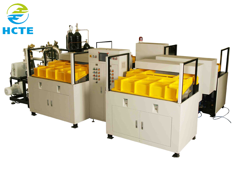
Normally when doing water resistant testwith a machine, one machine could only do one or two tests, like IPX1 only or IPX5 and IPX6 at the same time, but here is a system can handle water resistant test from IPX1 to IPX8.
IPX1-8 water-resistant test program consists of top to bottom drip rain evaluating equipment, oscillating tubing tester for IPX3 and IPX4, apply nozzle, handheld jet nozzle, smart normal water provide and manage program, IPX8 normal water tightness strain tester and tiltable turning phase.
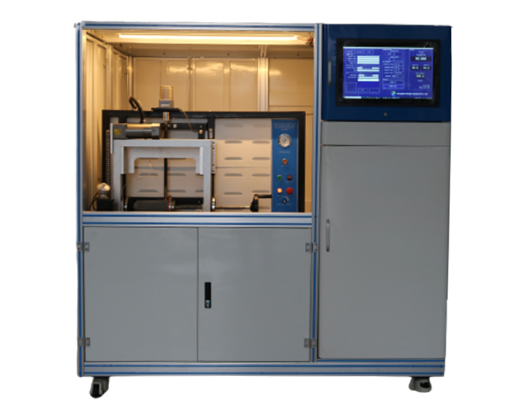
Vacuum Chamber-Type Helium Leak Detection Equipment is an advanced leak detection device that is based on helium mass spectrometry leak detection technology. It is specifically designed to detect minute leaks in various components or systems. The following is a detailed description of this equipment:
Equipment Structure
The equipment mainly consists of a vacuum box, a vacuum pumping system, a helium charging system, a helium mass spectrometry leak detector, and a control system.
Vacuum Chamber: A sealed container used to place the test piece. A high vacuum environment can be created inside the vacuum chamber to facilitate the detection of minute leaks. Vacuum Pumping System: Includes a vacuum pump and related piping and valves, used to extract air from the vacuum chamber to achieve the required vacuum level. Helium Charging System: Used to introduce a certain amount of helium gas into the test piece or vacuum chamber. Helium is an inert gas with small molecules that can easily penetrate through minute leak holes. Helium Mass Spectrometry Leak Detector: The core component of the equipment, used to detect the amount of helium gas leaking from the test piece. It utilizes the principle of mass spectrometry to detect the presence of helium with high sensitivity. Control System: Used to control the operation of the equipment, including automated control of vacuum pumping, helium charging, and detection steps.
Working Principle
Place the test piece inside the vacuum chamber and close the sealed door of the vacuum chamber. Activate the vacuum pumping system to extract air from the vacuum box and achieve a certain vacuum level. Introduce a certain amount of helium gas into the test piece or vacuum chamber through the helium charging system. Activate the helium mass spectrometry leak detector to start detecting the amount of helium gas leaking from the test piece. Judge the leakage situation of the test piece based on the detection results of the helium mass spectrometry leak detector.
Equipment Features
High Precision: Adopts advanced helium mass spectrometry leak detection technology, capable of accurately measuring the leak rate of the test piece with small errors. High Efficiency: The equipment has a high degree of automation, simple and quick operation, and can rapidly complete leak detection tasks. Safe and Reliable: The equipment is designed reasonably, equipped with various safety protection measures, and can ensure the safety of operators. Wide Application Range: Suitable for test pieces of various shapes and sizes, widely used in electrical, electronic, aerospace, communication, chemical, and other industries.
Applications
Vacuum Chamber-Type Helium Leak Detection Equipment has a wide range of applications in multiple fields, such as:
Aerospace: Used to detect leaks in aerospace equipment such as airplanes and rockets, ensuring flight safety. Electrical and Electronic: Used to detect leaks in electrical and electronic products such as electronic components and circuit boards, ensuring product quality. Communication: Used to detect the sealing performance of communication equipment, ensuring the stability and reliability of equipment in harsh environments. Chemical: Used to detect leaks in chemical equipment, preventing the leakage of harmful substances from causing environmental pollution.
In summary, Vacuum Chamber-Type Helium Leak Detection Equipment is a high-precision, high-efficiency, safe, and reliable leak detection device with broad application prospects and market value.
2021 is the first year of the rise of new energy vehicles. The global intelligent vehicle market maintains rapid growth, "intellectualization" has become the most important development idea of the industry. At present, the automobile industry is no longer a state of clear boundaries, and the trend of intelligent and lightweight automobile seats has become an irreversible inevitable trend.
Gas detection technology has a wide range of applications, in which a typical gas leak detection system is used to detect the tightness of the workpiece to be inspected. The external structure of the existing gas leak detection system includes several main components, such as an organic frame, a tracer gas source, a tracer gas inflation valve, a pressure sensor, a detection chamber, a leak detection valve, a return valve and a gas leak detector.
One of the detection methods is the chamber type gas leak detection system. The chamber type gas leak detection technology generally uses halogen gas, hydrogen or helium as the tracer gas, fills the tracer gas into the workpiece to be inspected, and uses the gas leak detector to detect the concentration of the tracer gas outside the workpiece to be inspected. If the detected tracer gas signal exceeds the set value of the gas leak detector, it indicates that the workpiece is leaking.
Chamber type gas leak detection system can be divided into vacuum chamber type gas leak detection system and atmospheric chamber type gas leak detection system. The working principle and structure of atmospheric chamber type gas leak detection system include tracer gas source, tracer gas inflation valve, detection chamber, leak detection valve, return valve and gas leak detector. The workpiece to be inspected is placed in the detection chamber, and the workpiece to be inspected is connected with the tracer gas source through the connecting pipe. During detection, after the door of the detection chamber is closed, the tracer gas inflation valve connecting the workpiece to be inspected is opened, and the tracer gas is filled into the workpiece to be inspected. The pressure sensor detects that after the inflation pressure in the workpiece to be inspected reaches a certain value, the tracer gas inflation valve is closed, and the leak detection valve and return valve are opened at the same time. If the workpiece to be inspected leaks, the gas in the workpiece to be inspected will overflow from the leak hole and enter the detection chamber under the effect of differential pressure. The gas leak detector samples from the detection chamber and judges whether the workpiece leakage exceeds the standard according to the size of the tracer gas signal obtained.
For the vacuum chamber type gas leak detection system, there is a vacuum pump and a vacuum valve connected to the detection chamber. Before the tracer gas is filled, there is no need to vacuum the detection chamber for the atmospheric chamber type gas leak detection system.
The main features of the chamber type gas leak detection system are high leak detection accuracy, fast production rhythm and simple operation.
The sampling space of the chamber type gas leak detection system is the space of the detection chamber and the relevant pipe space connected with the gas leak detector. Before the tracer gas is filled in the chamber type gas leak detection system, the gas in the clean sampling space is the reference background, and the tracer gas signal left in the sampling space after detection is called background noise. The tracer gas in the background noise may leak into the sampling space from the gas leak detection system itself, or it is the residual accumulation of the previous detection. The background noise of the tracer gas will increase with the repeated operation of the system. When the background noise exceeds a certain level, it will lead to the failure of the leak detector to operate normally, and even lead to false judgment of the detection results. The existing technology cannot effectively eliminate the residual accumulation of tracer gas, and it is usually necessary to eliminate the impact of background noise through repeated empty machine operation. The equipment operation efficiency is low, resulting in energy waste.
Gas detection technology has a wide range of applications, in which a typical gas leak detection system is used to detect the tightness of the workpiece to be inspected. The external structure of the existing gas leak detection system includes several main components, such as an organic frame, a tracer gas source, a tracer gas inflation valve, a pressure sensor, a detection chamber, a leak detection valve, a return valve and a gas leak detector.
One of the detection methods is the gas hood type gas leak detection system. The gas hood type gas leak detection system uses halogen gas, hydrogen or helium as the tracer gas, fills the tracer gas into the detection chamber (i.e. the gas hood), and uses the gas leak detector to detect the concentration of the tracer gas in the workpiece to be inspected. If the tracer gas index is detected to exceed the set value of the gas leak detector, it indicates that the workpiece to be inspected has leakage.
The working principle and structure of the above gas hood type gas leak detection system include a tracer gas source, a tracer gas inflation valve, a detection chamber (i.e. a gas hood), a workpiece connecting pipe, a leak detection valve, a return valve, and a gas leak detector. The backflow valve is connected with the gas leak detector, and the detection chamber is connected with the tracer gas source through the connecting pipe. After the door of the detection chamber is closed, the tracer gas inflation valve is opened, and the tracer gas is charged into the detection chamber. When the pressure sensor detects that the inflation pressure of the detection chamber reaches a certain value, the tracer gas inflation valve is closed. Open the leak detector and return valve. If the workpiece to be inspected leaks, the gas in the detection chamber (i.e. the gas hood) will overflow from the workpiece leak hole into the workpiece to be inspected under the effect of differential pressure. The gas leak detector samples from the internal space of the workpiece to be inspected, and judges whether the workpiece leakage exceeds the standard according to the size of the tracer gas signal obtained.
The main features of the gas hood type leak detection system are high leak detection accuracy, fast production rhythm and simple operation.
The sampling space of the gas hood type gas leak detection system is the internal space of the workpiece to be inspected, the workpiece connecting pipe and the relevant pipe space connected with the gas leak detector. Before the tracer gas is filled, the gas in the clean sampling space is the reference background of the gas hood type gas leak detection system, and the tracer gas signal remaining in the sampling space after detection is called background noise. The tracer gas in the background noise may leak into the sampling space from the gas leak detection system itself, or it is the residual accumulation of the previous detection. The background noise of the tracer gas will increase with the repeated operation of the system. When the background noise exceeds a certain level, it will lead to the failure of the leak detector to operate normally, and even lead to false judgment of the detection results. The existing technology cannot effectively eliminate the residual accumulation of tracer gas, and it is usually necessary to eliminate the impact of background noise through repeated empty machine operation. The equipment operation efficiency is low, resulting in energy waste.
When we want to do a structural integrity verification and bubbling point test for hydraulic filters, we may want to do it by a machine automatically. Then a test stand complying with ISO 2942-2004 may be suitable for doing the test.
It specifies a bubble-point test method for confirming the manufacturing dependability of your filter factor or figuring out the localization in the most significant pore in the filter factor by figuring out the first bubble point. Verification of manufacturing dependability specifies the acceptability in the filter aspects for additional use or tests. The first bubble noint is recognized throuah continuation in the manufacturing intearity testIt is under no conditions an operating sign of a filter element in specific. It cannot be employed for extrapolation for the ideas of purification ranking, performance or maintenance capacity and really should be used for details only.