Bridge Mills A Comprehensive Guide to Precision Manufacturing

Introduction

Today, bridge mills are an indispensable tool for manufacturers in industries like aerospace, automotive, energy, and heavy machinery. Bridge mills are increasingly used as engineering designs become more complex and the need for enhanced stability, precision and flexibility to machine large and heavy workpieces to extremely tight tolerances continues. As a rigid overhead bridge structure with multi axis capabilities, bridge mills offer high precision cutting compared to traditional knee mills or gantry mills.

In this article, we will look at how bridge mills can produce continuous production of complex components that can’t be made with smaller machines. Whatever your R&D work or high volume manufacturing needs, bridge mills provide a flexible solution to maximize productivity and minimize errors.


What is a Bridge Mill?

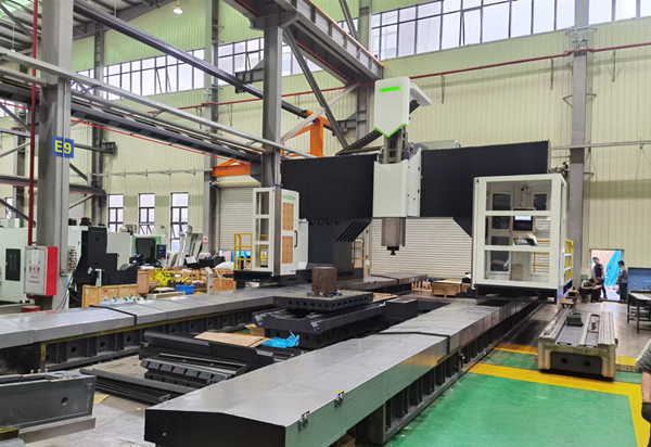
A bridge mill uses a huge overhead bridge assembly to support the spindle and worktable instead of a column or gantry. The spindle is held as it moves in X, Y, and Z axes by the bridge as a rigid support arm and the worktable below is positioned relative to the cutting tool.

This overhead arrangement leaves the entire area beneath the bridge open for oversized parts and assemblies, allowing much larger workpieces than could fit on a traditional vertical mill. Bridge mills derive their name from the bridge-shaped beam that spans the work area.

The key components of a bridge mill are:

● Bridge - The large overhead beam that supports the spindle slide and provides damping against vibrations. It contains the mechanisms to position the spindle in X and Y.

● Spindle - The rotating shaft that holds the cutting tool. It is powered by a motor inside the spindle slide with up to 50 hp. High torque spindles allow fast removal of material.

● Table - The large stationary or moving platform that supports the workpiece. It provides a precision mounting surface and T-slot holds for clamps and fixtures.

● Column - A fixed vertical member at one end that helps support the bridge. The column may house controls or services.

● Saddle - The moving transverse component mounted to the underside of the bridge. It positions the spindle slide in the Y-axis across the width of the table.

● Spindle Slide - The carriage assembly that traverses back and forth along the bridge in the X-axis, positioning the spindle over the workpiece.

Compared to gantry or knee mills, bridge mills are significantly heavier and bulkier, with a main bridge that is much more rigid thanks to its continuous cast iron or welded steel overhead design. This mass and stability is crucial for absorbing cutting forces and dampening vibration that could compromise precision.

The rigid construction also minimizes deflection of the spindle during aggressive material removal, enabling much tighter tolerances. When machining large components made of tough materials like steel or titanium, the stability of a bridge mill is vital to achieve chatter-free results. Their overhead configuration also allows practically unlimited workpiece sizes.


Types of Bridge Mills
Bridge Mills 

Bridge mills are available with different axis configurations and levels of automation to suit a wide range of applications:

2-Axis Bridge Mills

The simplest bridge mill design has two linear axes allowing motion in the X (longitudinal) and Y (transverse) directions. This provides positioning of the workpiece beneath the spindle for basic 2D operations like facing, drilling, boring, and end milling of flat surfaces. While limited in versatility, 2-axis bridge mills are an affordable option for high-volume production of large but basic parts, as their range of motion is sufficient for straightforward machining.

3-Axis Bridge Mills

A 3-axis bridge mill adds a Z-axis that raises and lowers the spindle vertically. This permits angled milling operations like helical interpolation, allowing the machining of bevels, tapers, contours, and angled features. The additional axis provides the ability to machine in 3 dimensions instead of just 2. Manufacturers gain greater flexibility to produce more complex components with a 3-axis bridge mill.

5-Axis Bridge Mills

On a 5-axis bridge mill, the spindle head tilts and rotates on two additional rotary axes in addition to moving linearly in X, Y, and Z. This enables the spindle to approach the workpiece from practically any orientation rather than just vertically. 5-axis motion facilitates high-precision machining of complex 3D surfaces and contours in a single setup, saving tremendously on time and cost. Many aerospace and impeller components require 5-axis milling due to their intricate blended or sculpted geometries.

Automated Bridge Mills

Modern computer numerical control (CNC) bridge mills allow all machining operations to be precisely programmed ahead of time. This allows push-button automation of repetitive cutting procedures with minimal operator intervention. The computer control precisely choreographs and executes tool paths for mass production. Automated tool changers, pallet changers, and robotic part load/unload systems can further enhance productivity for lights-out manufacturing across multiple shifts.


Key Features and Components of Bridge Mills 

Massive Work Area

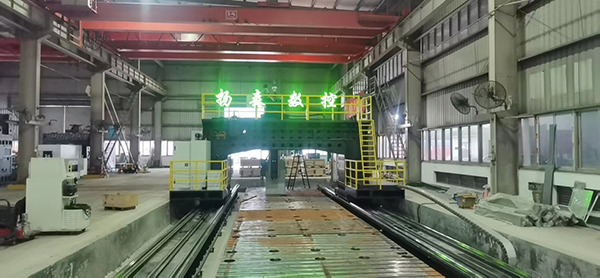
The cantilevered overhead design of a bridge mill leaves the entire area beneath the spindle open for oversized parts and assemblies. Common table sizes range from 5 x 10 ft up to 20 x 60 ft for gigantic components weighing over 100 tons. Huge motors drive the table through precision roller or hydrostatic ways. This expansive work zone minimizes setups by allowing batch machining of multiple large parts or entire weldments in a single fixture.

Rigid Bridge Assembly

Weighing up to 100,000 lb, the continuous overhead bridge utilizes a rigid box-way construction that resists deflection and damps vibration far better than jointed column or gantry mills. This stability prevents tool chatter, allows heavier cuts, and enables highly accurate motion of the spindle carriage across wide spans. Even minimal vibration can degrade precision and surface finish.

Powerful Spindles

High torque spindles up to 50 hp are common on bridge mills to power through hard alloys and remove material quickly from large parts. Higher rotational speeds up to 15,000 rpm provide ideal cutting speeds for optimized tool life and surface finish. The spindle cartridge is preloaded for thermal stability and minimal runout.

Precise Positioning

Ballscrews on the X, Y, and Z axes have high lead precision for accurate positioning and repeatability within 0.001”. Backlash is eliminated through preloading. Precision ground box ways or linear guides maintain tight geometrical tolerances when moving heavy components.

Multi-axis Capability

Optional rotary axes expand the range of possible milling operations by allowing angled cuts and 5-axis interpolated motion. Tilting the spindle facilitates machining of complex 3D contours, sculpted surfaces, and intricate blade geometries in a single setup.

Automated Features

Bridge mills equipped with CNC, tool changers, pallet shuttles, robotic part handling, automatic lubrication, and more enable lights-out manufacturing for maximum productivity. Hundreds of parts can be machined without operator intervention across multiple shifts.


Applications of Bridge Mills
 

Aerospace Industry

Aircraft construction relies on large monolithic components like wings, frames, and bulkheads milled from aluminum, titanium, or composites. Landing gear, turbines, transmission housings, and other assemblies also demand high precision. Bridge mills offer the work envelope and accuracy needed for these high-value aerospace components with delicate instrumentation.

Automotive Industry

Automakers machine engine blocks, cylinder heads, crankshafts, transmission cases, axles, wheels, and body components from large steel or aluminum castings and weldments. Bridge mills maintain tight tolerances on these heavy parts while removing material quickly. Their high rigidity suits the noisy environment.

Heavy Machinery

Massive excavator booms, bulldozer track links, hydraulic cylinders, press frames, and other oversize parts require stable bridge mills to withstand vibrations inherent in heavy machining. They excel at removing substantial material from thick castings and fabrications.

Mold Making

Larger injection molds, die cast dies, and foundry patterns demand the precision of bridge mills to accurately produce contoured cavities without distortion. Their work volume readily accommodates even enormous 400-ton plastic or metal molds. Tight process control optimizes molded part quality.

Energy Industry

Turbines, compressors, reactors, valves, offshore platform components, and more leverage the long travels and precision of bridge mills during manufacturing. The mills maintain quality standards for these expensive parts operating in extreme conditions.


Benefits of Using Bridge Mills

Precision

The stability provided by the rigid overhead bridge enables extremely tight tolerances, even when machining large parts from vibration-prone materials like titanium or nickel alloys. Chatter is avoided, allowing smooth, accurate cuts.

Versatility

Available in different sizes and with varying axis configurations, bridge mills can handle a wider range of materials and part geometries compared to smaller mills. Their heavy-duty build allows machining everything from stainless steel to composites.

Cost Savings

While bridge mills require a greater upfront investment, they maximize productivity and minimize operating costs on large components. Their ability to consolidate several operations in one setup saves tremendously on fixtures, tooling, programming, and quality inspections.

Improved Throughput

Continuous cuts across expansive work zones result in shorter cycle times. Pallet changers and part loading/unloading automation further boost throughput for high-volume production across multiple shifts, improving asset utilization.

Reliability

Industrial bridge mills are built for round-the-clock operation in harsh conditions. They stand up to heavy use with minimal downtime. Many operate reliably for decades after proper installation, maintenance, and training.


How to Choose the Right Bridge Mill

Workpiece Size

Consider current and future maximum part dimensions to ensure the mill will accommodate them with room for fixturing and tooling. A too-small machine will severely limit capability.

Axis Configuration

The type and complexity of required milling operations determines the ideal number of axes. 5-axis mills offer the most application flexibility and reduce setups through multisided machining but are costlier.

Spindle Power

Ample spindle power prevents slowdowns or stalling when removing substantial material. Higher torque spindles with 15,000+ rpm allow faster hogging and finishing feeds/speeds. Ensure power meets demands.

Precision Standards

More expensive machines generally offer greater accuracy through more precise ballscrews, way quality, vibration dampening, and thermal stability. Evaluate precision needs carefully.

Automation Plans

Consider pallet changers, robotic part handling, tool changers, CNC programming, and other automation upfront rather than difficult retrofitting later. This optimizes lights-out production.

Service and Support

Reliable local service and technical support will maximize uptime and productivity. Ensure the machine builder has a proven reputation for quality and customer care.


Common Challenges with Bridge Mills 

Vibration Control

Excessive vibration during heavy duty milling can cause chatter, accuracy issues, poor surface finish, and reduced tool life. Careful fixturing, balanced tooling, adaptive feed control, and smooth ramping of spindle speed help mitigate vibrations.

Thermal Effects

Frictional heat during machining causes components to expand, altering dimensions. Chillers and coolant systems counteract thermal growth. CNCs can also compensate by altering cutter paths based on temperature sensors.

Tool Wear

Abrasive alloys quickly degrade cutting tools. Advanced tool materials, coatings, proper selection of speeds/feeds, and indexed inserts all help combat wear. In-process gauging can automatically adjust for loss of tool diameter.

Maintenance Needs

Bridge mills have thousands of moving components requiring regular lubrication, inspection, and service for optimal reliability. Skilled technicians should track and perform preventative maintenance.

Space Constraints

Bridge mills have massive footprints, heights, and weights demanding substantial floor space, reinforced foundations, and rigging equipment. Facilities must carefully plan layouts to accommodate their bulk.


Future Trends in Bridge Mill Technology

Automation and AI Integration

Smart machine monitoring with artificial intelligence promises even greater productivity through predictive maintenance, troubleshooting, adaptive control, and automated inspection. The mills will become self-optimizing.

Multi-tasking Capability

Next-generation bridge mills will incorporate turning, grinding, drilling, tapping, and other capabilities on one platform for complete production of complex parts in a single setup. Hybrid machine tools will continue gaining traction.

Advanced Materials

More manufacturers are adopting hard-to-machine materials like titanium, Inconel, and composites. Future spindles, tools, programming, and controls will be optimized for these exotic materials.

Sustainable Design

Eco-friendly lubrication systems, intelligent sleep modes, hybrid drives, and through-spindle coolant will be incorporated for energy and fluid efficiency. Bridge mills are getting greener.


Conclusion

Bridge mills with their huge work areas, superb stability and multi axis flexibility allow manufacturers to increase precision, productivity and agility when making large complex parts. They are leaders in optimizing output, quality and consistency for critical aerospace, automotive and heavy industry parts.

Bridge mills are a greater upfront investment, but the long term savings of reduced setups, improved workflow and increased throughput are huge. Bridge mills will only grow in strategic importance as engineering components become bigger and more sophisticated. Strong consideration should be given by companies seeking to maximize manufacturing capabilities, capacity, and competitiveness to the use of bridge mills. Their advantages are unique, enabling manufacturers to do what is not possible on smaller machines.
How to choose curved guides and linear guides

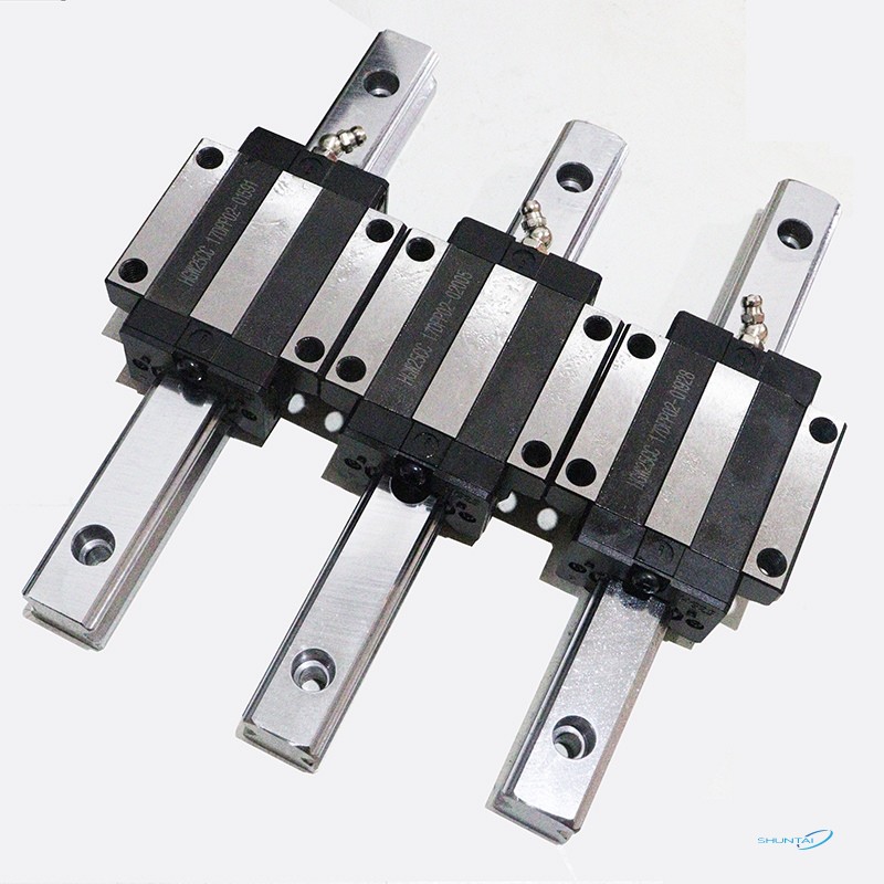
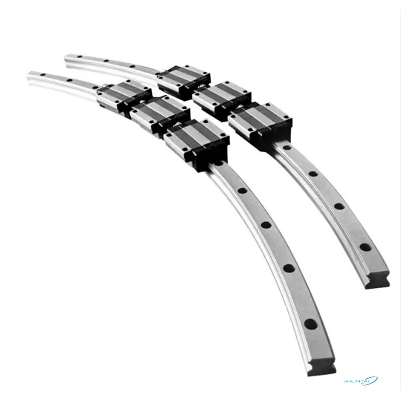
Curved guides and linear guides are two common types of guides. Both have support and guidance functions. Both can transfer the energy of movement to the receiving end to achieve stable movement. So what is the difference between the two?

From a structural point of view, linear guides are in the shape of a straight line, and they play a role in positioning, supporting and guiding in the movement of machinery and equipment. Curved guides are a special circular structure that is widely used in hardware, automation and precision mechanical equipment, and can maintain the axis position of relative movement unchanged.

From the perspective of motion trajectory, the movement mode of linear guides is linear motion driven by balls. The contact area between the balls and the guide grooves is small, so that the surface of the guide is evenly stressed and has a long life cycle. The arc guide realizes movement by the rolling of the balls on the curved surface of the guide. The curved surface of the guide bears a larger contact area, so the load capacity is higher than that of linear guides.  

From the application point of view, linear guides are widely used in CNC machine tools, semiconductor equipment, medical equipment and other fields due to their linear motion characteristics. They can provide high-precision, high-rigidity and low-friction motion control, and are suitable for high-speed and high-precision linear motion requirements.

Curved guides are more suitable for occasions that require curved motion or circular interpolation, such as robots, aerospace equipment, precision measuring instruments, etc. They can achieve smooth curved motion and precise circular interpolation, improving the motion performance and positioning accuracy of the equipment.

The above is the difference between linear guides and circular guides. When choosing guides, users in the machinery industry should choose the appropriate guide form according to the specific usage scenarios and needs to ensure the stability and reliability of the mechanical equipment.

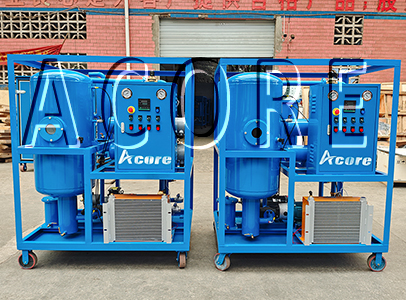
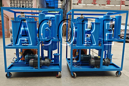
VHF100(6000LPH) Hydraulic Oil Filtration Machine Sales to Mid East Country

We design, produce and sales two sets of VHF100(6000 liters per hour) Hydraulic Oil Filtration Machine to Mid East country. The Hydraulic Oil Filter Machine is important for the hydraulic system with its precise filtration technology and high filtration efficiency. It adopts advanced filter materials, such as steel screen, polymer fiber filter element, etc., which can efficiently intercept and remove particles, moisture, the vacuum dehydration and degassing system can remove water, gases and harmful substances to ensure the purity and stability of the hydraulic oil. Hydraulic Oil Filtration Machine not only reduces wear and corrosion inside the hydraulic system, but also significantly improves the operating efficiency and stability of the system.


VHF Hydraulic Oil Filter Machine can greatly extend the service life of hydraulic system. In the hydraulic system, the presence of impurities and contaminants will accelerate the aging of the oil and the wear and tear of the equipment, resulting in the degradation of equipment performance and frequent failures. By regularly using a hydraulic oil filter machine, the contaminant content in the oil can be effectively reduced, and the cleanliness and performance of the oil can be kept stable, thereby slowing down the wear rate of the equipment and prolonging the service life of the equipment.


The Hydraulic Oil Filtration Machine also has the advantages of easy operation and easy maintenance. It adopts automatic control systems, which realize the functions of one-button operation and automatic cleaning, which greatly reduces the labor intensity and maintenance costs of operators. VHF Hydraulic Oil Filtration Machine can ensure the stable operation of the hydraulic system and prolonging the service life with its precise filtration technology, excellent filtration effect and convenient operation and maintenance characteristics.

Hydraulic Oil Filtration Machine

Hydraulic Oil Filtration Machine

DVTP Vacuum Transformer Oil Treatment Machine Sales to Algeria

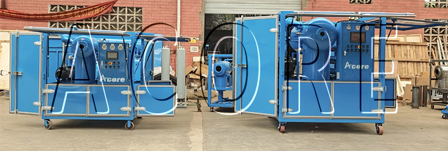
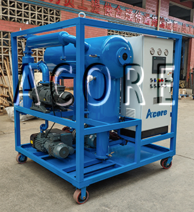
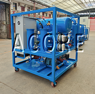
Acore Filtration Co.,Ltd sales two sets of DVTP Vacuum Transformer Oil Treatment Machine to Algeria, one is 3000L/H and another is 12000L/H machine. Both machines install the weather-proof canopy for water and dust protection. Meanwhile, the client also buy two sets of portable oil filter cart for oil filling and transferring. The main functions of transformer oil are insulation, cooling, and arc extinguishing. However, transformer oil can be contaminated and oxidized during prolonged use, especially after exposure to air, which can affect its performance. Therefore, oil purification processing is a key measure to ensure the normal operation of the transformer and extend its service life.


The main purpose of oil purification processing is to remove impurities such as moisture, gases, and solid particles from transformer oil to restore its insulation properties and cooling effect. Generally, the Transformer Oil Treatment Machine includes vacuum oil purification for dehydration and degassing, oil filtering for removing particles and regeneration for removing acid and color.


In addition to regular Oil Purification Processing, there are a few precautions that can be taken to extend the life of your transformer oil. For example, maintaining the sealing performance of the transformer to prevent the ingress of external contaminants and moisture; Regularly check the oil level and oil temperature of the transformer to ensure that it is within the normal working range; As well as regular maintenance and maintenance of transformers, timely detection and treatment of potential problems.


How long the transformer oil needs to be filtered is a complex issue that needs to be considered comprehensively according to the actual situation. By regularly monitoring the performance of the oil, taking appropriate precautions, and carrying out timely oil purification processing, the stable operation of the transformer and the extension of its service life can be ensured. At the same time, it is also very important for the operation and maintenance personnel of the power system to understand and master the performance of transformer oil and its treatment methods. Only in this way can we ensure the safe and reliable operation of the power system and provide a solid power guarantee for the development of social economy.

Vacuum Transformer Oil Treatment Machine

GRT-50 SF6 Gas Treatment Machine Sales to Spain

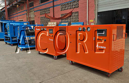
Acore Filtration Co.,Ltd manufacture 2 sets of GRT-50 SF6 Gas Treatment Machine to Spain, Europe, which has function of recovery, purification, filling, vacuum evacuation and storage. GRT-50 gas treatment machine is mainly used for GIS electric equipment.


GRT SF6 Gas Recovery System adopts mobile type with new technology, new design, full function, reasonable structure, simple and easy operation. The main functions as following:

1. Measurement of vacuum pumping and vacuum degree of the device and electrical equipment.

2. Recover the gas in the electrical equipment.

3. Dry and purify the recovered and recharged SF6 gas.

4. Inflatable SF6 electrical appliances.

5. Compress and store SF6 gas in electrical appliances.


Features:

1. The design is high-tech, the function is complete, the structure is reasonable, and the operation is concise and clear.

2. Compression system: SF6 air compressor, no leakage.

3. The vacuum system adopts a two-stage rotary vane vacuum pump, and there is an automatic anti-oil return device in the system.

4. The purification system adopts the principle filter of CKD company in Japan, and the filter adopts electric heating and built-in high-efficiency adsorbent, and the purification effect is more significant (no need to replace the adsorbent frequently).

5. Automatic confirmation of three-phase power supply in the electrical system of the device, automatic protection of phase failure.

6. The device control system adopts the SF6 special valve with the latest technology

7. The storage system is equipped with liquid storage tank according to user requirements.

8. The equipment adopts mobile type.

SF6 Gas Treatment Machine

DVTP100 Transformer Oil Purification Machine Sales to Canada

Acore Filtration Co.,Ltd manufactures and sales a set of DVTP100(6000 liters per hour) Double Stages High Vacuum Transformer Oil Purification Machine to client in Canada, the client bought a set of DVTP100 machine in 2023 and was very satisfied with quotation machine, so he buy the machine again in 2024. The client is a transformer manufacturer, they do transformer oil purification after they install the transformers at site.


DVTP100 Transformer Oil Filter Machine can quickly remove water, gas and impurities in the insulating oil, reduce dielectric loss, and improve the insulation performance and oil quality of the oil. It can effectively ensure the normal operation of power equipment and avoid accidents. Meanwhile, the Transformer Oil Filter Machine can meet the installation or maintenance site of the transformer body vacuuming, and at the same time complete the oil dehydration and degassing processing of the transformer oil, which shortens the oil processing period. the oil dehydration plant integrates precision filtration, efficient dehydration, degassing, vacuum three-dimensional evaporation technology and automatic control technology of oil, which is simple to operate, safe and reliable in operation.

DVTP Transformer Oil Dehydration Plant also adopts high filtration precision, large dirt holding capacity, can remove fine suspended particulate matter in oil. Its unique degassing and dehydration materials, the evaporation area is hundreds of times larger than that of conventional materials.This Transformer Oil Filter Machine has the characteristics of high efficiency, easy to move and is especially suitable for live operation on site. DVTP Transformer Oil Dehydration Plant also adopts advanced oil temperature controlling system, which can arbitrarily set the upper and lower limits of oil temperature to achieve interval control of oil temperature. High degree of automation, automatic control and automatic protection of oil level guarrantee safe and reliable, simple and convenient operation of transformer oil purification machine.

Transformer Oil Purification Machine Transformer Oil Purification Machine

What a powerful container shear!

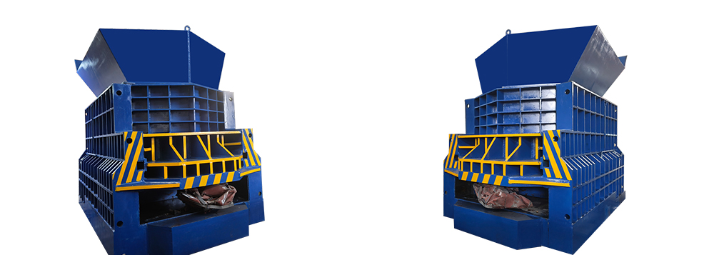
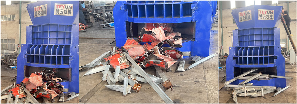
We are specializing in the production of metal scrap shear for metal recycling. Our container shear machine is horizontal type and it's suitable for cutting metals with different cross-sectional shapes in the cold state. Horizontal automatic container shear is very suitable for cutting metals of different cross-sectional shapes in cold state, such as round, square, slot, angle, I-shaped, plate and various scrap structural metals. It brings convenience to the packaging, storage and transportation of scrap metal materials, and also provides qualified furnace charge for smelters.

Features:


The box shear machine has a wide range of applications and is a processing equipment for metal recycling stations, factory foundries and mechanical construction industries.


1.Container machine adopts hydraulic drive, you can choose manual or PLC automatic control operation. Automatic control can save human energy.

2.Production capacity up to 15 -20tons per hour

3.Eco friendly no gases required.

4.HARDOX is used as wear resistant plates

5.Blades are made up of graded tool steel for high wear resistance and long life.The scrap feed in hopper, due to the movement of pre clamp the scrap automatically slips down and the cut scrap is pushed out from the front.

6.Continuous raw material feed

7.Lesser space required.

8.The installation does not require any foundation or foot screw.

How to maintain and service hydraulic alligator shears?(1)

Hydraulic alligator shears are essential in various industrial fields such as scrap metal processing and manufacturing.

Regular maintenance is essential to ensure the life and effectiveness of key components. This article provides a detailed guide on maintaining and servicing the main components of hydraulic alligator shears.


1. Maintaining the cutting blade

Regular inspection and sharpening: Regularly check the blade for dullness or damage. Sharpen the blade as needed to ensure smooth cutting and relieve stress on the machine.

Replacement: If the blade is excessively worn or damaged, replace it in time to avoid affecting the efficiency and safety of the machine.

2. Press cylinder

The press cylinder is responsible for the driving force of the shear to cut the material.

Seal inspection: Frequently check the hydraulic seal for wear or leakage. If necessary, replace the seal to prevent fluid leakage and maintain pressure.

Rod condition: Check for wear, corrosion or misalignment on the cylinder rod. A damaged rod can lead to inefficient operation and safety hazards.

3. Press plate

The press plate holds the material in place during the cutting process.

Alignment check: Make sure the press plate is aligned with the cutting blade for optimal performance.

Surface inspection: Check regularly for any cracks or wear, and repair or replace the platen if it is damaged.

4. Motor

The motor powers the hydraulic pump and needs to be checked regularly to ensure it is operating efficiently.

Cooling system: To prevent overheating, keep dust and debris out of the motor's cooling system.

Electrical connections: Check all electrical connections for signs of wear or corrosion. Secure any loose connections and replace damaged wires or components.

5. Valves

The pressure and flow of the hydraulic oil are managed through hydraulic valves.

Operational testing: To ensure the valves are operating properly, test them regularly. Be alert for unusual sounds that may indicate potential problems.

Cleaning: Keep the valves clean and free of debris buildup that can cause the valves to stick or malfunction

6. Cutting cylinders

Like press cylinders, cutting cylinders are used for cutting, so similar care is required.

Leakage checks: Make sure the hydraulic oil level is correct and perform regular leak checks.

Pressure tests: Check the hydraulic pressure in the cutting cylinder regularly to ensure it meets the specifications required for efficient operation.

7. Pumps

The machine's hydraulic oil must move, so a hydraulic pump is needed.

Oil Level and Quality: Check the hydraulic oil level regularly and top up as needed. Replace the oil if it is contaminated.

Pump Inspection: Listen for noise changes and check for vibrations, which may indicate wear or misalignment.

8. Electric Box

The electric box contains the electrical components that control the machine.

Moisture and Dirt: Make sure the electric box is free of moisture and dirt, which can cause electrical failures.

Component Inspection: Frequently check all components inside the electric box for signs of wear or damage. Replace any damaged components immediately.

9. Oil Tank

The oil tank stores the hydraulic oil required for the machine to operate.

Cleanliness: Keep the oil tank clean and ensure that the oil is not contaminated by debris or water, which can damage the hydraulic system.

Gaskets and Seals: Check the seals and gaskets that attach to the oil tank for signs of degradation or perforation and replace them accordingly.

10. General Maintenance Tips

Routine Cleaning: Clean the entire machine regularly to prevent the accumulation of debris and dirt, which can affect the operation of the machine and cause premature wear.

Lubrication: Apply lubricant to moving parts as directed by the manufacturer to ensure seamless function.


Regular maintenance is essential to the life, efficiency and safety of hydraulic alligator shears. Regular inspection and maintenance of components such as cutting blades, cylinders, motors and valves prevents breakdowns and optimizes performance.

TEYUN Horizontal Baler Description(1)

TEYUN Horizontal balers are used for recycling of waste paper, plastics, PET bottles and cans. This series of balers can be configured with hoppers and can be fed with conveyors or manually according to customer needs. We can also provide engineering design and help to simplify customers' work and improve overall efficiency. Advantages The wide hopper opening is suitable for large and hollow materials. The hydraulic drive has the advantages of stable operation, high pressure and high efficiency. Good appearance, compact structure, high efficiency, simple operation, safe and reliable. The baling size can be built according to customer requirements!


Horizontal baler is also known as carton baler, waste paper strapping machine, waste paper processing equipment, the equipment is used in the normal state of waste paper and similar products extruded firm, and packaged with a special packaging tape molding, so that its volume is greatly reduced, so as to achieve the purpose of reducing the volume of transportation, saving freight costs, and increase the benefits for the enterprise. The company's waste paper baler and carton strapping machine processing equipment introduces the advanced technology and advanced process of similar products at home and abroad.


Advantages of waste paper horizontal baler:

Waste paper horizontal baler has good rigidity and stability, beautiful and generous modeling, easy to operate and maintain, safe and energy-saving, low investment cost of equipment infrastructure projects and so on. It is widely used in all kinds of waste paper factories, old things recycling company and other units of enterprises, suitable for the old waste paper, plastic straw and other baling and recycling, is to improve labor efficiency, reduce labor intensity, save manpower, reduce transportation costs of good equipment.

How to maintain the slurry pump on a daily basis?


The following is the first part of the daily operation and maintenance of slurry pumps: tart-up and shutdown:

Preparations Before Start-up:

Check whether the connecting bolts and foundation bolts of the pump are loose.

Check whether the piping connection is proper and whether the centers of the pump and the driver are aligned. For pumps handling high-temperature or low-temperature liquids, the expansion and contraction of the piping may cause shaft misalignment, seizure, etc. Therefore, flexible pipe joints, etc., should be used.

Direct coupling and alignment. For small-sized pumps handling normal-temperature liquids, there is no problem in aligning the pump and the motor when the pump is stopped. However, for large-sized pumps handling high-temperature liquids, there is a large difference in the shaft center during operation and stoppage. To achieve correct alignment, generally heat to the operating temperature or stop the pump after the operation and quickly re-align to ensure that the shaft centers of both rotating parts are the same and avoid vibration and pump seizure.

Clean the piping. Before operation, the piping must be cleaned first to remove foreign objects, welding slag, etc. from the piping. Do not let foreign objects or welding slag fall into the pump body. Install pressure gauges before and after the strainer in the suction pipe to monitor the clogging of the strainer during operation.

Barring. Remove the coupling before start-up, turn the rotor by hand to observe whether there are any abnormal phenomena, and conduct a separate test run of the motor to check whether its rotation direction is the same as that of the pump. By rotating the coupling by hand, it can be found whether there are foreign objects between the impeller and the casing inside the pump. The barring should be even in weight, and there should be no abnormal noise inside the pump.

Start the oil pump and check whether the bearing lubrication is good.

Priming the pump. Fill the pump chamber with liquid before start-up to discharge air, liquefied gas, and steam from the suction pipe and the pump body.

Start-up:

The idle operation must be avoided. At the same time, open the suction valve, and close the discharge valve and each discharge hole.

Open the cooling water supply valve for the bearings.

If the stuffing box has a water jacket, open the cooling water supply valve of the stuffing box.

If the pump handling high-temperature liquid has not reached the working temperature, open the preheating valve, and close this valve after the pump is preheated.

If the pump is equipped with a liquid-sealing device, open the valve of the liquid-sealing system.

If equipped with an overheating device, open the bypass valve of the self-circulation system.

Start the motor.

When the pump flow increases and overheating is no longer possible, close the valve of the self-circulation system.

If the pump must be started with the check valve closed and the outlet gate valve open, the start-up steps are basically the same as the above method, except that the outlet gate valve should be opened for a period of time before the motor is started.

Gradually open the discharge valve.

Shutdown:

Open the valve on the self-circulation system.

Close the discharge valve.

Stop the motor.

If it is necessary to maintain the working temperature of the pump, open the preheating valve.

Close the cooling water supply valves of the bearings and the stuffing box.

If liquid-sealing is not required during the shutdown, close the liquid-sealing valve.

If it is a special pump device requirement or when the pump is opened for inspection, close the suction valve, and open the vent hole and various discharge holes.

Usually, the start-up and shutdown steps specified for turbine-driven pumps are basically the same as those for motor-driven pumps. Turbines have discharge valves, various drain holes, and sealing devices, which must be opened or closed before and after operation. In addition, turbines generally require preheating before start-up. Some turbines in the system are required to be started at any time, so barring operation is required. Therefore, the operator should operate according to the relevant regulations on the start-up and shutdown steps of the turbine provided by the turbine manufacturer.

Maintenance During Shutdown For standby pumps at the chemical plant site, when the in-use pump fails, they should be able to be switched over in time and put into normal operation to ensure that the chemical production process is not interrupted. This requires the maintenance of the standby pumps to keep them in good condition during the standby and shutdown period. Especially for standby pumps with interlock and automatic switching, their inlet and outlet valves are open, and the pumps are filled with the medium to be transported. As long as the driver rotates, they can start working immediately.

For standby pumps during the shutdown period, the quality and quantity of the lubricant should be checked frequently. The pump body and the medium inside the pump that needs to be heated and insulated should be heated and insulated. To prevent the rotor from bending due to its own weight and to prevent the shaft from adhering to the bearings and causing start-up difficulties, the standby pumps should be barring regularly.

For pumps that have been shut down for a long time, open the plugs on the pump body to drain the liquid inside the pump to avoid damage to the pump body due to cold weather. If necessary, open the pump body, clean the internal parts, and apply anti-rust oil. For pumps that have been shut down for a long time, whether they are on-site or in the warehouse, they should be barring regularly.

For details of the first part, please refer to the next blog post.