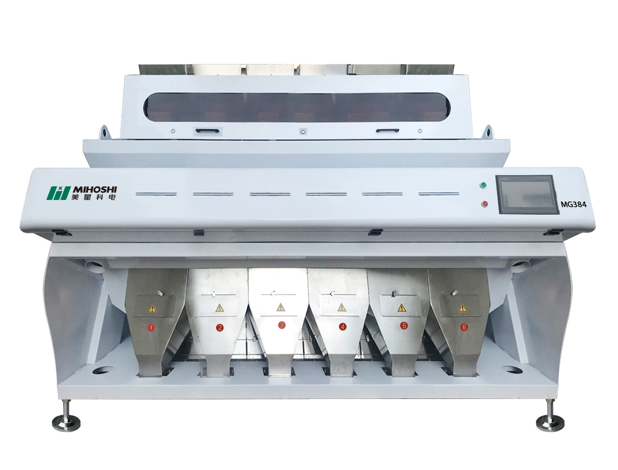
Choosing Between Direct Connected Spindle and Belt Type Spindle!

Introduction

Choosing Between Direct Connected Spindle and Belt Type Spindle! This blog analyses core disparities. Performance and maintenance features are discussed.

As for the DCS and the BTS, the two come with their own pros. Find out which spindle is fit for you. Performance of your machine depends on this choice that you make. Stay tuned for comprehensive studies.


What Are the Core Differences Between Direct Connected and Belt Type Spindles?

· Operational Mechanisms

The direct connected spindle has a motor shaft connected directly to the spindle shaft.

This setup ensures minimal vibration. In a belt type spindle power transmission is achieved using a belt drive which is based on pulleys and belts.

Models with direct connection provide high precision with fewer moving parts. Belt type is a versatile option that comes with different pulley ratios. Both are suitable for specific applications in machining.

· Speed Control

The uniform speed of the spindles comes from the direct motor-shaft linkage. These spindles allow the machines to operate at high speed. The variable pulley diameters used in this type of spindles play an important role in speed adjustment, making them more flexible.

The speed stability of these systems is affected by the belt tension. Directly connected systems attain constant speeds flawlessly. The two spindles were intended to handle different machining.

· Torque Transmission

A straight connected countershaft transmits the torque right from the motor reducing power losses. These spindles ensure consistent torque. Belt spindles transmit torque through belts and pulleys, with a risk of slippage. Torque consistency can have issues of belt wear.

Direct connected systems make sure prompt torque transfer. Both have specific advantages depending on the application.

· Cost Efficiency

The issue with the direct connected spindles is that they are more expensive for their complicated design at first. Maintenance is usually less often. Belt type spindles are inexpensive to begin with, and their components are easier to change also.

These spindles might demand more frequent maintenance. Indirect systems are cheaper but less stable. Such devices regulate budgeting between performance and specific purposes.


How Do Direct Connected Spindles Enhance Machine Performance?

· Precision Levels

Precise direct connected spindles (DCS) decrease backlash to achieve higher levels of accuracy. They achieve ±0.001mm accuracy. The run out of BTS (belt type spindles) is greater than that of MLT. DCS employ high quality servo motors with rotational speed exceeding 10,000 rpm.

Pulley and belt are the resources the band BTS leverages. During DCS, the shaft alignment is made meticulously. BTS can experience misalignment.

An advanced feedback loop of the encoder is provided by DCS. Positioning BTS has limited accuracy. DCS systems mitigate thermal contraction and expansions effects. BTS belts, unfortunately, begin wearing out over time. The DCS ensures a better pose fix.

BTS introduces vibration. DCS provides improved repeatability. BTS requires frequent maintenance. A DCS is ideally for super precise jobs. BTS struggles with micro-movements. A DCS integrated system leads to repeatable machining results.

· Efficiency Boost

DCS, the direct connected spindles, make manufacturing process efficient in a way that the pin is closer to the ground. They use high-powered servo motors that are high in efficiency.

Spindles in Belt type (BTS) are susceptible to energy wastage through belts. DCS has direct power transmission which means that there is no signal loss from changes in voltage and current. BTS involves mechanical friction. DCS is functionally characterized by shorter response time.

BTS problem is caused by the mistimed torque transmission. DCS monitoring specifies constant rpm. BTS systems have tensions which are adjusted for some belts whereas for others tensions do not change.

DCS creates less maintenance outage, in contrast. BTS needs belt replacement on a regular basis since this part is constantly in contact with the wheel. DCS supports continuous operation.

BTS experiences slippage issues. DCS provides the most sophisticated cooling system. BTS has bad cooling performance. DCS maximizes power utilization. BTS operates less efficiently.

· Speed Variability

The direct resistance connected spindles (DRCS) have the advantage of speed variability. They are responsible for changing rpm dynamically. Belt type spindles (BTS) have small velocity ranges because of their design. DCS, on the other hand, employs VFD.

BTS works with transmission ratio fixed and the ratio is constant. DCS can regulate the rpm operation and the range is from low to high. The speed shifter in BTS will require manual attentiveness.

One virtue of DCS is its smoothness during the switching. The speed consistency is the major negative accompanying the BTS. DCS systems basically play a role in adaptive speed control.

Due to its mechanical limitation, BTS is subjected. DCS allows for quick generation speed changes, thus decreasing downtime associated with speed changes. It calls for several stopovers to rectify alignment.

ATC improves the accuracy between different cruise speeds. BTS lacks flexibility. The DCS is flexible enough to adjust to different raw material characteristics.

· Torque Consistency

The direct connected spindles called the Direct Connected Spindles (DCS) transmit torque output steadily. These robots feature servo-driven actuators with advanced precision.

Belt-type spindles (BTS) correspond with these torque fluctuations. DCS has constant torque throttle all through rpm range. At speeds over 80 miles per hour, the vehicle will encounter torque drops.

DCS better when it comes to the notion of load adjustment. Expansion of the belt is a direct influence on BTS. DCS systems include the feedback loops too.

There is a shortfall in the immediate generation control for BTS. DCS is declared accurate with respect to the torque. BTS structures have embedded slippage problems. DCS supports heavy-duty machining.

BTS is designed for maximum torque and acceleration. DCS minimizes mechanical wear. BTS system should be improved continually. The DCS eliminates the pulsing by providing the appropriate torque smooth delivery.

· Operational Stability

While direct connected spindles (DCS) create operation stability, they also guarantee grinding operations uninterrupted. They help to be anti-vibration, low in noise.

BTS type spindles (BTS) are vibration producing to the level of being dangerous. DCS is using the balanced structure motor. The ski lift mechanism in BTS is improperly designed, causing imbalances.

DCS provides consistent performance. DCS provides damper technology to avoid the negative effects of un-damped vibration modes. The BTS does not incorporate an advanced vibrational control mechanism. DCS enhances cutting quality. BTS compromises surface finish.

DCS supports high-speed machining. BTS limits operational speeds. DCS ensures long-term reliability. BTS has to exchange part instrumental frequently. DCS minimizes unplanned downtimes.

BTS involves more maintenance. DCS systems ensure the structural integrity of all affected structures.

Criteria

Direct Connected Spindles

Belt Type Spindles

Precision Levels

High precision (±0.001 mm)

Moderate precision (±0.01 mm)

Efficiency Boost

Higher efficiency (90%+)

Lower efficiency (70-80%)

Speed Variability

Wide range (500-40,000 RPM)

Limited range (500-10,000 RPM)

Torque Consistency

Consistent torque delivery

Variable torque

Operational Stability

High stability, less vibration

Moderate stability, more vibration

Table on How Do Direct Connected Spindles Enhance Machine Performance!


What Advantages Do Belt Type Spindles Offer in Industrial Settings?

· Cost Savings

The type of spindle with a belt (BTS) reduces initial investment costs. They have cheap pulleys systems. Higher motor costs are associated with the direct connected spindles.

BTS offers cost-effective maintenance. DCS requires expensive components. BTS has very basic mechanical parts. DCS requires the creation of tailor-made servo motors.

BTS systems decrease operating expenses. DCS increases maintenance costs. BTS offers a low cost alternative to erecting pylons and transmission lines. DCS employs expensive direct drive machines. BTS is the advantage of small manufacturers having low-cost.

· Flexibility Increase

Another advantage of Belt type spindles (BTS) is their versatility in speed control. They adjust the pulley size. Direct connected spindles (DCS) have predetermined speed ranges.

BTS allows easy accelerations. DCS needs complex programming. BTS systems became suitable for various machining operations. DCS lacks this flexibility.

BTS is particularly adaptable for processing a wide variety of materials. DCS is less adaptable. BTS enables easy customization. DCS has limited adjustability. BTS enhances operational versatility.

· Maintenance Ease

Belt-type spindles (BTS) develop ease of repair and maintenance. They replace the belts without any trouble. Spindles which are directly linked (DCS) have to use specially designed pieces of equipment. BTS systems require schedule disrupted as little as possible.

DCS involves complex repairs. BTS is designed for simple belt changes. DCS necessitates motor recalibrations. BTS components can be easily bought everywhere.

DCS parts are especially rare. BTS reduces service intervals. DCS demands frequent check-ups. BTS ensures straightforward troubleshooting.

· Environmental Suitability

BTS spindles operate well in severe conditions. They put up with dust and dirt. Direct connected spindles (DCS) require environment with lower discharges. BTS systems mediate temperature changes.

DCS experiences thermal variation problems. BTS uses the components that are resistant to mechanical stresses. DCS requires sensitive electronics.

BTS is reliable for industrial environments and networks. DCS suits controlled environments. BTS stands for avoiding interruptions in factory operation. DCS is more delicate. BTS makes the best of it in adverse conditions.


When Should You Choose a Direct Connected Spindle Over a Belt Type Spindle?

· High Precision

Where more precision is required, use direct connected spindles (DCS). DCS achieves ±0.001 mm accuracy. More run-out for the belt type spindles (BTS) is also observed. DCS uses high-resolution encoders. Lack of precise BTS systems limits its effectiveness.

DCS is capable of mitigating thermally induced shrinkage. BTS experiences thermal drift. DCS assembles the stable shaft alignment. Over time the angle of BTS will deviate. DCS ensures consistent accuracy. BTS struggles with micro-movements. DCS boasts on high precision tasks.

· Enhanced Durability

Choose DCS for excellent durability. DCS is equipped with the servo motors of the highest performance. Belt drive spindles (BDS) are belted and hence risky. DCS components are in accordance with the high loads. BTS parts wear quickly. DCS offers advanced cooling systems.

BTS heat is not efficiently controlled. The DCS systems require low maintenance. BTS involves belt replacement frequently. DCS ensures long-term reliability. BTS involves regular servicing. DCS provides superior longevity. BTS components degrade faster.

· Optimal Speed

Opt for DCS option for highest speed attainment. DCS incorporates the use of variable-frequency drives. Fixed pulleys create spindles with belt type (BTS). DCS provides a modified curve of rpm settings.

BTS offers various manual speed adjustments. CNC systems, however, are capable of high-speed machining. BTS still has the bottleneck problem.

DCS provides rapid acceleration. BTS experiences unavoidable speed transition sluggishness. DCS ensures a steady speed during drifts. BTS cars have speed irregularities. DCS enhances machining efficiency.

· Superior Torque

Selecting direct drive spindles (DCS) will provide the highest torque. DCS is characterized by providing constant torsion. Belt type spindles (BTS) are torque-variation sensitive. DCS facilitates constant torque throughout the rpm range. The far torque of BTS is attenuated when speed is higher.

DCS uses precision-engineered motors. BTS is subject to the pulling strength. DCS supports heavy-duty machining. BTS faces the problem of relative high-torque.

The DCS control systems use real time torque control. BTS lacks such precision. DCS delivers careful linear torque. BTS experiences slippage.

· Critical Applications

In regard to critical functions, opt for direct connected spindles (DCS). DCS ensures precise performance. The belt-type spindles (BTS) are not dependable. DCS supports high-precision tasks.

BTS struggles with accuracy. DCS maintains stable operation. BTS experiences frequent misalignment. DCS systems have more elaborate feedback cycles. BTS lacks real-time monitoring.

DCS is particularly notable in critical surroundings. BTS falters under stress. DCS provides consistent results. BTS requires constant adjustments. Exactness is a DCS benefit while being used for crucial machining.

Criteria

Direct Connected Spindles

Belt Type Spindles

High Precision

Required (±0.001 mm)

Not critical (±0.01 mm)

Enhanced Durability

Long lifespan, low maintenance

Shorter lifespan, higher maintenance

Optimal Speed

Necessary for high-speed operations

Sufficient for lower speed needs

Superior Torque

Essential for heavy-duty tasks

Acceptable for light tasks

Table on When Should You Choose a Direct Connected Spindle Over a Belt Type Spindle!


What Are the Maintenance Implications for Each Type of Spindle?

· Routine Checks

Directly connected spindles (DCS) are always thoroughly visually examined. Such procedures include motor inspection and encoder calibration. The belt type spindles (BTS) require for belt tightening. DCS systems require sensor alignment to be operated regularly. In BTS, pulley wears need to be inspected.

DCS check-ups relates to thermal management. BTS inspection is to ensure the belt is not damaged. DCS requires vibration monitoring. BTS needs to be frequently replaced as the belt wears out.

DCS makes use of modern diagnostics. BTS prefers faster checking techniques. DCS ensures long-term accuracy.

· Lubrication Needs

Spindles connected via direct current (DCS) have very few lubrication requirements. They use sealed bearings. Belt-type spindles (BTS) require periodic belt lubrication. DCS systems utilize auto lubricating parts. BTS requires periodic oiling. DCS operates with an advanced grease removal system.

BTS demands manual lubrication. DCS enhances the grease life performance. BTS lubrication significantly impacts belt life. DCS uses high-efficiency lubricants.

BTS employs standard oils. DCS reduces maintenance intervals. BTS requires regular inspection of its lubrication.

· Component Wear

Direct connected spindles (DCS) do not wear out components easily. They use precision-engineered parts. Belt type spindles (BTS) are a common cause of belt wear.

DCS systems contain rugged bearings. The BTS incorporates the replacement belts. DCS lowers wear down by means of the direct drive system. BTS has disadvantage of belt stretch.

DCS is made of hardened steel shafts. BTS uses rubber belts. DCS reduces maintenance costs. BTS usually entails frequent parts replacing. DCS contributes to longer part life.

· Operational Lifespan

Unlike other connected spindles, direct connected spindles (DCS) have a longer usable lifespan. They are servo motor-based. Belt type spindles (BTS) have shorter lifetimes.

DCS systems use resistant components. BTS parts wear quickly. DCS is thus superior to the traditional convection ovens since it is more efficient in thermal management.

BTS lacks efficient cooling. DCS stays performance over the time. BTS experiences gradual degradation. DCS need a lesser number of repairs. BTS involves regular maintenance. DCS offers consistent operation.


Conclusion

Selecting between Direct Connected Spindle and Belt Type Spindle! We discussed the issues of accuracy, quickness, and long-term survival. DCS ensures accuracy and durability that other devices do not. BTS can help to cut cost and increase flexibility. Maintenance needs vary significantly.

Each spindle type has tailored specific benefits. Your choice affects the general quality of the machine's performance. Consider all factors carefully. Visit CNCYANGSEN for expert advice. Choose your spindle right by today!


FAQs!

Q: Why Should You Choose Direct Connected Spindle For High-Precision Tasks?

A: Direct Connected Spindles (DCS) has an outstanding performance in accuracy and error is controlled within ±0.001mm precision. They prevent cold chilling and thermal expansion, resulting into high level of accuracy thus making them suitable for every precision machining job.

Q: How Does Maintenance Differ Between Direct Connected Spindle And Belt Type Spindle?

A: Direct-connected spindles (DCS) have an advanced diagnostic system that does not need an express maintenance. Belt-type spindle (BTS) requires a more frequent upkeep which includes regular belt replacement and lubrication.

Q: Which Spindle Type Offers Better Durability In Harsh Environments?

A: DCS operates very well in terms of the toughness thanks to the utilization of advanced materials and sealing bearings. The belt type spindles (BTS) maintain high efficiency but due to belt wear constraints, their operating life is relatively short.

Q: How Do Operational Loads Affect Direct Connected Spindle And Belt Type Spindle?

A: In direct connected spindles (DCS) high-torque servo motors are capable of processing dynamic loads with uniform torque. Silent or Hi-torque spindles (BTS) are not effective under high loads and vary most. 

How CNC Lathe Technology is Helping with the Manufacturing Sector

Are you looking to increase your production capabilities and stay ahead of the competition? Computer Numerical Control (CNC) technology is something you should surely opt for. According to the National Institute of Standards and Technology (NIST), CNC technology increases production efficiency by up to 85%, making it a pivotal force in modern manufacturing. Specifically, it has brought better parts and high accuracy to the manufacturing floor, including the use of CNC lathes. The present article focuses on the advantages of the CNC lathe machine, how its use enhances production, and how one can compare vertical and horizontal CNC lathes.

We will also learn how CNC technology improves the machining process and help you identify the suitable lathe machine for your business.


What is the Basic Principle of a CNC Lathe Machine?


CNC lathe is a machinery developed to perform cutting, boring, and turning operations on materials with high precision and speed. As opposed to conventional techniques, CNC lathes incorporate specific computational ascetics to regulate numerous factors of the matter. This cuts down on the involvement of human intervention, which may lead to the making of errors and hence enhances the accuracy of the machining done.

CNC lathe machines are basically used to hold the workpiece against a turning tool, which rotates the workpiece while cutting, drilling, and threading at the same time. CNC lathe machines are available in either vertical or horizontal configurations, depending on the requirements for the particular task at hand, and each has its unique strengths.


Vertical vs. Horizontal CNC Lathe: Selecting the Best Lathe Machine


Vertical CNC Lathes:

Instructions

Typical Values

Working

Spindle Speed Range (RPM)

20 - 3,500 RPM

Suitable for large workpieces, slower due to part size.

Maximum Cutting Speed (m/min)

150 - 400 m/min

Provides good cutting efficiency for more significant components.

Spindle Motor Power (kW)

22 - 55 kW

Higher power supports heavy-duty operations.

Maximum Workpiece Diameter (mm)

1,500 - 3,000 mm

Designed for more extensive, heavy workpieces like gear blanks.

Maximum Workpiece Weight (kg)

5,000 - 15,000 kg

Supports heavier parts due to vertical structure.

Axis Travel (Z-axis)

1,000 - 2,000 mm

Vertical travel supports deep drilling.

Tool Turret Speed (Tool Change Time)

0.5 - 2.5 sec

Efficient tool change improves machining cycles.

Surface Roughness

1.6 - 3.2 µm

Good surface finish for large-diameter parts.


A CNC lathe machine is a sophisticated piece of equipment meant to help execute turning, boring, and cutting of different materials in an exact manner. Another significant difference is that the CNC lathes do not use manual controls as do the conventional ones. Instead, they feature computer systems that interface to control several parameters of the machining procedure.

The primary use of a CNC lathe is to turn a piece of material against a center with a cutting tool, which cuts, bends, or drills the required shape accordingly. CNC lathe machines can be vertical or horizontal according to the working requirements; every structure has suitable machining applications.


Horizontal CNC Lathes:

Specifications

Typical Values

Working

Spindle Speed Range (RPM)

50 - 6,000 RPM

Higher speeds for cylindrical parts and small workpieces.

Maximum Cutting Speed (m/min)

250 - 600 m/min

Higher cutting speeds for mass production.

Spindle Motor Power (kW)

18 - 45 kW

Suitable for medium to high production demands.

Maximum Workpiece Diameter (mm)

400 - 800 mm

Designed for smaller, high-speed production parts.

Maximum Workpiece Weight (kg)

500 - 3,000 kg

For lighter, high-precision components like shafts.

Axis Travel (Z-axis)

700 - 1,200 mm

Horizontal travel for elongated parts like rods

Tool Turret Speed (Tool Change Time)

0.2 - 1.5 sec

Faster tool changes for higher throughput.

Surface Roughness

0.8 - 1.6 µm

Excellent surface finish for precision components.


The horizontal CNC lathe employs features like precision marble beds and hydro-static spindles, and it is lightweight with particle damping to achieve high accuracy. These characteristics help to improve dynamic performance in that; there is a reduction in the vibration level and a higher natural frequency hence; desirable machining performance.

Specialized Horizontal CNC Lathes

Some of the specialized horizontal CNC lathes include automobile steering bars with machining fixtures, whereby specific spindle boxes support the design, hence minimizing labor. These lathes have horizontally positioned spindles, which makes them suitable for turning long cylindrical products like shafts. They are also suitable for mass production due to their stiffness in use, high cutting speeds, and easy chip removal.


Choosing Between Vertical and Horizontal Lathes:

The type of CNC lathe used, vertical or horizontal, depends on the dimensions of the workpiece, its difficulty level, and the batch production required. Vertical CNC lathes are unique for rigid, large, or complex workpieces due to their high torque and compact structure, although some machines may vibrate.

However, horizontal CNC lathes provide better accuracy and faster cutting to improve the production of low-cross-sectional, cylindrical goods. While the vertical lathe is designed for specific use in areas such as automotive, the horizontal lathe is widely used in almost all fields.


How Do CNC Lathes Enhance Precision and Efficiency?

1. Lightweight CNC Lathes and Vibration Control for Precision Manufacturing

CNC Lathes with new lightweight construction and Particle Damper Technology allow excellent performance and lower vibration. They decrease their weight by up to 50 pounds as much as possible. 8% makes them more efficient in high-speed productions without compromising accuracy. This enhanced mode of vibration control enhances the finishing of the surface and durability of tools, which is essential in industries such as aerospace and automobile. This is appreciable in vertical and horizontal CNC lathes, making the operations smooth and efficient.

2. Enhanced Machining Accuracy and Faster Setup with CNC Programming

Computer numerical controlled programming helps to guarantee high Machining accuracy to minimize tool path deviations that may cause errors in the parts. Such accuracy is crucial within industries such as aerospace and automotive, where part and component dimensions are significantly regulated. However, the setup times are also reduced with the CNC lathes since they can be quickly reprogrammed, and hence, the lathe's productivity is superior to that of conventional machines.

3. Multifunctionality and Hybrid CNC Machines for Versatility

Many different operations, such as turning, thread cutting, drilling, etc, are possible with attachments on a CNC lathe. Turning & milling hybrid CNC machines compile both turning and milling operations in a single setup and provide a broader range of geometries than conventional turning systems. It also increases flexibility and performance in aerospace, metalworking, and automotive fields.

4. Automation and Optimized Cutting Speeds for Production Efficiency

Automation of CNC lathe machines reduces manual interferences and decreases errors as the machines work accurately. Higher cutting speeds that are achieved and regulated according to mechanical properties improve the cycle time and longevity of the cutting tools. This, coupled with automation and optimized speeds, makes manufacturing operations more efficient, controls the cost of labor, and makes manufacturers more competent.

5. Precision Manufacturing and Vibration Control for Quality Parts

CNC lathes provide greater accuracy in dimensions, which is paramount in manufacturing medical equipment and aircraft, among others. Proper control of vibrations helps to have even surfaces and makes tools last long. Since it has integrated control for the tension of the belt used in the CNC lathes, the machining is steady, and there is no uneven production of parts of low quality, hence minimizing wastage.


What are the Applications of CNC Lathe Technology?


1. Machine Shop Programming

Turret-type CNC lathes are especially useful for many machine shop computer programming applications. They are proficient in chucking and bar processing, enabling various machining. These skills are beneficial when handling several setups with a lot of delicacy, making them very useful in machine shops. CNC lathe technology increases production by automating time-consuming processes, hence crucial in industries requiring high precision.

2. Additional Attachments and Versatile Operations

Components like grinding spindles to CNC lathes can introduce a new level of functional versatility. This enables a CNC lathe to attain and grind operations within a single setting. Such attachments must be run with the assistance of high-level software to manage the grinding wheel's operation. Such versatility enables the CNC lathes to perform various machining requirements while proving the versatility of modern CNC technology.

3. Surface Roughness Control and High Precision

New methods in CNC lathe technology, such as artificial neural networks (ANN), determine surface roughness. Satisfactory surface finishes and the dimensional accuracy required for the workpiece can, therefore, be realized through optimization of cutting parameters using predictive models on CNC lathes. This high precision is essential in sectors where the flatness of the surface and dimensions are crucial factors. From applying ANN to CNC lathes, this paper also demonstrates how the technology improves machining steadiness and output quality.

4. Educational Models and Accessibility

Developing affordable CNC wood lathes is one of the viable ways ITTN can spread the use of CNC technology, especially in learning institutions. These models can significantly minimize the cost of production and occupation space and serve as a helpful learning apparatus for students and hobbyists. Due to new light and cheap designs, the educational institution can provide practical experience with CNC lathes and acquire a better understanding of precise machining and automation.

5. Lightweight Designs and CAM Integration

Lightweight designs, including integrating linear motors in CNC lathes, enable sub-micron positioning accuracy. An increase in speed precision increases high-speed operation and also overall machining performance. Also, Computer Aided Manufacturing (CAM), when implemented along with the CNC lathes, optimizes the programming processes and enhances the performance by achieving better accuracy in the machining process and part fabrication. The advancements in CNC lathe technology prove the role of the technology in producing optimal results in manufacturing.


What are the Benefits of CNC Lathe Machines for Manufacturing? 

1. Improved Machining Precision and Higher Productivity

CNC lathes are precision machines that provide accurate machinery or operations, usually demanded by the aerospace and automotive industries. ORIZATION ensures that every part of the product is machined to a required level of accuracy minus human interference. In the same respect, CNC lathes do not undergo regular downtimes; hence, they can work for long and produce high volumes in equal measure. In this method, several parts can be machined simultaneously, increasing efficiency.

2. Multipurpose Use in Machining Processes and Labour Savings

CNC lathes are flexible; they can cut, drill, thread, and perform boring operations on this lathe type. This means that they can be used for a small number of workers, as those found in a small workshop, and for a relatively large number of workers, as may be found in manufacturing industries. Furthermore, automation in CNC lathes lowers the demand for skilled personnel as almost all operations are carried out by the machine. This reduces the expenses on employees while at the same time ensuring an organization retains or improves the quality of its productions.

3. Consistency, Repeatability, and Increased Efficiency

Traditional lathes take substantial time to produce numerous similar parts with high accuracy and consistency. In contrast, CNC lathes give consistency, allowing one to get a thousand similar parts without much deviation. This is important in industries where product standardization is necessary, especially throughout large batch production. The positive performance of CNC lathes makes it easier to improve productivity and meet high-quality demands, making them crucial components of modern output.


What are some of the Best CNC Lathe Machines for Manufacturers? 

1. HAAS Automation

Based in the United States of America, HAAS Automation is a reputable CNC lathe machine producer that produces highly durable and accurate lathes suited for different sectors. It is made to offer CNC machining solutions to companies, enabling enhanced efficiency in the lathe machines primarily used in complicated exercises. Due to this flexibility, HAAS Automation’s horizontal and vertical CNC lathes provide a solution for aerospace and automotive industries with their needs for precision and performance.

2. DMG Mori

It is well-established for manufacturing several flexible CNC lathe machines with the latest CNC technology for lathe machines. Its vertical and horizontal CNC lathes tackle high-speed machining and have many advantages in lathe manufacturing. These machines are particularly advantageous in organizations that have a standard need for devices that are presumed to perform at exceptionally high levels of capacity while at the same time being versatile; therefore, the reason why companies seeking to enhance their precision machining needs go for these machines.

3. Okuma

Okuma’s CNC lathe machines also have the highest level of precision, making them suitable for precision manufacturing. They provide technology that enhances manufacturing operations, such as automated CNC programming. Okuma’s machines are commonly used in aerospace and automotive industries, where machining and lathe machines are essential in manufacturing high-quality parts with small tolerances.


How does CNC Lathe Technology Boost Productivity? 

1. Automation and Minimizing Human Error

CNC lathe technology optimizes workpiece control and tooling while improving repeatability. This reduces or minimizes reliance on human operators, making CNC lathe machines more accurate and efficient. Since the CNC lathe initiates the operation, human error is eliminated, resulting in a high-quality finish, as required in precision machining industries.

2. High Precision, Consistency, and Improved Machining Stability

CNC lathes are precision machines capable of providing repeatability, crucial in producing components with complicated shapes and close tolerances. Sores and numerical controls are also regulated with servo control systems in state-of-the-art CNC lathe machines to improve machining stability. This makes the CNC lathe machines vital for accurate machining and lathe machine effectiveness in manufacturing.

3. Increased Efficiency and Faster Production Cycles

Efficiency is another significant benefit of implementing lean manufacturing since it enables the production of larger goods in a shorter time.

CNC lathes have improved production by reducing the time spent setting up and actual output. Because they can easily alternate between tasks and maximize cutting speeds, they complete production more often and faster. This increases the overall efficiency of lathe production and reduces wastage, making CNC lathe machines suitable for large-scale production.

4. Versatile Operations and Time Savings

The CNC lathes’ flexibility is rightly justified because it can perform turning, drilling, and threading operations through various attachments. These benefits include integrating several functions into a single machine and reducing the time required to employ several machines. Usability in a way that allows for multiple operations in one setting makes CNC lathe machines more efficient in a range of manufacturing operations.

5. Cost Reduction and Operational Efficiency

CNC lathe machines cut costs by using one machine to perform multiple operations, reducing the production cost. Improved operating efficiency is obtained through better machine time balance and a lesser need for manual intervention. These changes make the CNC lathes indispensable for modern manufacturing, increasing productivity and competitiveness while reducing operational costs.

Elevate Your Living Experience with Customized Villa Elevators

As modern living spaces continue to evolve, the demand for convenient and luxurious home amenities increases. One such amenity that is gaining popularity among homeowners is the villa elevator. Designed to provide ease of movement within multi-level residences, villa elevators offer a range of benefits while enhancing the overall style and functionality of your home.

Elevate Your Lifestyle

Whether you reside in a spacious villa or a small house, adding a home elevator can transform the way you navigate your living space. No longer will you need to worry about climbing stairs or carrying heavy loads up and down multiple levels. With a villa elevator, you can effortlessly move between floors, making everyday tasks more convenient, especially for individuals with mobility challenges or elderly family members.

Customized for Your Needs

The beauty of villa elevators lies in their ability to be customized according to your unique preferences. From sleek and modern designs to timeless classics, there is a wide range of options available to suit your home’s interior aesthetics. With features like wood paneling, exquisite lighting, and ergonomic controls, these elevators seamlessly blend with your home’s overall decor, leaving a lasting impression on guests.

Smart Technology at Your Fingertips

In our technologically advanced world, it’s no surprise that villa elevators are becoming smarter too. Equipped with cutting-edge technology, these elevators offer enhanced safety and functionality. Imagine being able to control your elevator with a touch of a button or even through your smartphone. With smart elevator systems, you can easily summon the elevator to your desired floor, adjust the lighting, and monitor its status from anywhere in your home.

Residences of All Sizes

Contrary to popular belief, villa elevators are not limited to sprawling mansions alone. They can be seamlessly integrated into residences of all sizes, including small houses and compact apartments. With their small footprints and efficient design, these elevators provide a space-saving solution without compromising on style or functionality. So, even if you have limited square footage, a villa elevator can elevate your living experience and add value to your home.

Quality and Safety Assured

When it comes to residential elevators, safety is paramount. That’s why it’s crucial to choose CE certified products from trusted manufacturers. CE certification ensures that the elevator complies with rigorous safety standards, giving you peace of mind as you move between floors. With advanced safety features such as emergency stop buttons, door sensors, and backup power supply systems, villa elevators prioritize the well-being of their users.

The XSL Modern French Wood Home Elevator

Among the variety of villa elevator options available, the XSL Modern French Wood Home Elevator stands out as a luxurious choice. This elegant elevator combines the charm of French design with the richness of wood craftsmanship, creating a sophisticated and stylish addition to your home. With its smooth hydraulic operation and spacious interior, the XSL elevator offers a high level of comfort and convenience.

Elevate your living experience by investing in a customized villa elevator. Whether it’s a small house or a grand villa, the addition of a home elevator not only enhances accessibility but also adds a touch of luxury and sophistication to your living space. Choose a trusted manufacturer and explore the wide range of options available to find the perfect villa elevator that suits your style and elevates your lifestyle.

DHP120(120m3/h) Dry Air Generator Sales to Canada

DHP Air Dry Machine designed and manufactured by Acore Filtration Co.,Ltd sales to Canada, which mainly supply dry air when installing and maintaining the transformers, reactors and other large-scale power equipment. The dew point of dry air can reach -70°C. The Dry Air Generator can replace the traditional hot oil circulation, nitrogen supplementation, vacuum and other drying methods, and is more efficient, economical, safe and environmentally friendly.


The dry air machine device is mainly composed of four parts: air compressor, freeze drying system, adsorption drying system and electrical control system. The air enters the air storage tank through the air compressor, and most of the water is compressed and liquefied and discharged through the drain valve, and the air is sub-dried; After entering the refrigeration dryer, the water vapor is condensed into water, and the air is dried for the second time; Then enter the adsorption dryer for the third drying, adsorb the remaining trace water, and transport it to the equipment that needs to dry the gas through a high-precision air filter.


The dry air generator has the advantages of stable output pressure, low noise and strong purification ability, and is an ideal air source to replace high-pressure air cylinders. The product can not only meet the use of various types of domestic and imported gas chromatographs and various analytical laboratories, but also can be used as an air source for high-purity nitrogen generators. The Air Dry Machine is powered by a fully enclosed compressor, which purifies the natural air through three stages to remove water, oil and impurities in the air, and outputs stable and clean air through the pressure stabilizing device.


DHP Air Dry Machine


DHP Air Dry Machine

Application of Thermal Shock Test Chamber

Application of Thermal Shock Test Chamber

Thermal shock test chamber is an indispensable test equipment for aviation, automotive, home appliances, scientific research and other fields, used to test and determine the parameters and performance of electrical, electronic and other products and materials after temperature environment changes in high temperature, low temperature, alternating humidity and heat degree or constant test; Or constant humid heat test after the temperature environment changes the parameters and performance. Applicable to schools, factories, research positions, etc.

Thermal Shock Test Chamber

1, the high and low temperature impact test chamber with automatic, high-precision system loop, any part action, fully PLC locking processing, all use PID automatic calculation control, high temperature control precision, advanced scientific air circulation cycle design, make the indoor temperature uniform, avoid any dead corners; The complete protection device avoids any possible hidden dangers and ensures the long-term reliability of the equipment.

2, high and low temperature impact test chamber adopts advanced measuring device, and the controller adopts a large color LCD man-machine touch dialogue LCD man-machine interface controller, which is simple to operate, easy to learn, stable and reliable, and displays the complete system operation status, execution and setting program curve in Chinese and English. With 96 test specifications independently set, impact time 999 hours 59 minutes, cycle cycle 1~999 times can be set, can realize the automatic operation of the refrigerator, to a large extent to achieve automation, reduce the workload of the operator, can automatically start and stop working at any time.

3, The left side of the chamber has a test hole with a diameter of 50mm, which can be used for wiring test parts with external power load. Can be independently set high temperature, low temperature and cold and thermal shock three different conditions of the function, and in the implementation of cold and thermal shock conditions, you can choose two or three trough and cold flushing, hot flushing impact function, with high and low temperature testing machine function.

Comparison of Climatic Test and Environmental Test

Comparison of Climatic Test and Environmental Test

Climate environment test -- constant temperature and humidity test chamber, high and low temperature test chamber, cold and hot shock test chamber, wet and heat alternating test chamber, rapid temperature change test chamber, linear temperature change test chamber, walk-in constant temperature and humidity test chamber, etc. They all involve temperature control.

High and Low Temperature Humidity Test Chamber

Because there are multiple temperature control points to choose from, the climate chamber temperature control method also has three solutions: inlet temperature control, product temperature control and "cascade" temperature control. The first two are single-point temperature control, and the third is two-parameter temperature control.

Single point temperature control method has been very mature and widely used.

Most of the early control methods were "ping-pong" switch control, commonly known as heating when it's cold and cooling when it's hot. This control mode is a feedback control mode. When the temperature of the circulating air flow is higher than the set temperature, the electromagnetic valve of refrigeration is opened to deliver cold volume to the circulating air flow and reduce the temperature of the air flow. Otherwise, the circuit switch of the heating device is switched on to directly heat the circulating air flow. Raise the temperature of the air stream. This control mode requires that the refrigeration device and heating components of the test chamber are always in a standby working state, which not only wastes a lot of energy, but also the controlled parameter (temperature) is always in an "oscillation" state, and the control accuracy is not high.

Now the single-point temperature control method is mostly changed to the universal proportional differential integral (PID) control method, which can give the controlled temperature correction according to the past change of the controlled parameter (integral control) and the change trend (differential control), which not only saves energy, but also the "oscillation" amplitude is small and the control accuracy is high.

Dual-parameter temperature control is to collect the temperature value of the air inlet of the test chamber and the temperature value near the product at the same time. The air inlet of the test chamber is very close to the installation position of the evaporator and heater in the air modulation room, and its magnitude directly reflects the air modulation result. Using this temperature value as the feedback control parameter has the advantage of quickly modulating the status parameters of the circulating air.

The temperature value near the product indicates the real temperature environmental conditions suffered by the product, which is the requirement of the environmental test specification. Using this temperature value as the parameter of feedback control can ensure the effectiveness and credibility of the temperature environmental test, so this approach takes into account the advantages of both and the requirements of the actual test. The dual-parameter temperature control strategy can be the independent "time-sharing control" of the two groups of temperature data, or the weighted two temperature values can be combined into one temperature value as a feedback control signal according to a certain weighting coefficient, and the value of the weighting coefficient is related to the size of the test chamber, the wind speed of the circulating air flow, the size of the temperature change rate, the heat output of the product work and other parameters.

Because heat transfer is a complex dynamic physical process, and is greatly affected by the atmospheric environment conditions around the test chamber, the working state of the tested sample itself, and the complexity of the structure, it is difficult to establish a perfect mathematical model for the temperature and humidity control of the test chamber. In order to improve the stability and accuracy of control, fuzzy logic control theory and method are introduced in the control of some temperature test chambers. In the control process, the thinking mode of human is simulated, and the predictive control is adopted to control the temperature and humidity space field more quickly.

Compared with the temperature, the selection of humidity measurement and control points is relatively simple. During the circulation flow of the well-regulated humid air into the high and low temperature cycle test chamber, the exchange of water molecules between the wet air and the test piece and the four walls of the test chamber is very small. As long as the temperature of the circulating air is stable, the circulating air flow from entering the test chamber to exiting the test chamber is in the process. The moisture content of wet air changes very little. Therefore, the relative humidity value of the detected air at any point of the circulating air flow field in the test box, such as the inlet, the middle stream of the flow field or the return air outlet, is basically the same. Because of this, in many test chambers that use the wet and dry bulb method to measure humidity, the wet and dry bulb sensor is installed at the return air outlet of the test chamber. Moreover, from the structural design of the test box and the convenience of maintenance in use, the wet and dry bulb sensor used for relative humidity measurement and control is placed at the return air inlet for easy installation, and also helps to regularly replace the wet bulb gauze and clean the temperature sensing head of the resistance PT100, and according to the requirements of the GJB150.9A wet heat test 6.1.3. The wind speed passing through the wet-bulb sensor should not be lower than 4.6m/s. The wet-bulb sensor with a small fan is installed at the return air outlet for easier maintenance and use.


Comparison of Natural Convection Test Chamber, Constant Temperature and Humidity Test Chamber and High Temperature Oven

Comparison of Natural Convection Test Chamber, Constant Temperature and Humidity Test Chamber and High Temperature Oven

Instructions:

Home entertainment audio-visual equipment and automotive electronics are one of the key products of many manufacturers, and the product in the development process must simulate the adaptability of the product to temperature and electronic characteristics at different temperatures. However, when using a general oven or thermal and humidity chamber to simulate the temperature environment, either the oven or thermal and humidity chamber has a test area equipped with a circulating fan, so there will be wind speed problems in the test area.

During the test, the temperature uniformity is balanced by rotating the circulating fan. Although the temperature uniformity of the test area can be achieved through the wind circulation, the heat of the product to be tested will also be taken away by the circulating air, which will be significantly inconsistent with the actual product in the wind-free use environment (such as the living room, indoor).

Constant Temperature and Humidity Test Chamber

Because of the relationship of wind circulation, the temperature difference of the product to be tested will be nearly 10℃. In order to simulate the actual use of environmental conditions, many people will misunderstand that only the test chamber can produce temperature (such as: oven, constant temperature humidity chamber) can carry out natural convection test. In fact, this is not the case. In the specification, there are special requirements for wind speed, and a test environment without wind speed is required. Through the natural convection test equipment and software, the temperature environment without passing through the fan (natural convection) is generated, and the test integration test is performed for the temperature detection of the product under test. This solution can be used for home related electronics or real-world ambient temperature testing in confined Spaces (e.g., large LCD TV, car cockpits, automotive electronics, laptops, desktops, game consoles, stereos, etc.).

Unforced air circulation test specification :IEC-68-2-2, GB2423.2, GB2423.2-89 3.31 The difference between the test environment with or without wind circulation and the test of products to be tested:

Instructions:

If the product to be tested is not energized, the product to be tested will not heat itself, its heat source only absorbs the air heat in the test furnace, and if the product to be tested is energized and heated, the wind circulation in the test furnace will take away the heat of the product to be tested. Every 1 meter increase in wind speed, its heat will be reduced by about 10%. Suppose to simulate the temperature characteristics of electronic products in an indoor environment without air conditioning. If an oven or a constant temperature humidifier is used to simulate 35 °C, although the environment can be controlled within 35 °C through electric heating and compressor, the wind circulation of the oven and the thermal and humidify test chamber will take away the heat of the product to be tested. So that the actual temperature of the product to be tested is lower than the temperature under the real windless state. It is necessary to use a natural convection test chamber without wind speed to effectively simulate the actual windless environment (indoor, no starting car cockpit, instrument chassis, outdoor waterproof chamber... Such environment).

Comparison table of wind speed and IC product to be tested:

Description: When the ambient wind speed is faster, the IC surface temperature will also take away the IC surface heat due to the wind cycle, resulting in the faster the wind speed and the lower the temperature.


Definition and Characteristics of UV Weathering Test Chamber

Definition and Characteristics of UV Weathering Test Chamber

    Uv weathering test chamber is a professional equipment used to simulate and evaluate the resistance of materials to ultraviolet radiation and corresponding climatic conditions. Its core function is to simulate the effect of ultraviolet light on materials in the natural environment through artificially controlled ultraviolet radiation, temperature and humidity changes, so as to conduct comprehensive and systematic tests on the durability, color stability and physical properties of materials. In recent years, with the development of science and technology and the continuous improvement of material performance requirements, the application of UV weathering test chambers has become more and more extensive, covering plastics, coatings, rubber, textiles and other fields.

UV Weathering Test Chamber

    The characteristics of the equipment are mainly reflected in its high efficiency and accuracy. First of all, the UV weathering test chamber uses a high-intensity ultraviolet lamp, which emits an ultraviolet spectrum close to sunlight, which can accurately simulate the lighting conditions in the real environment. Secondly, it has a real-time monitoring and control system, which can precisely regulate the internal temperature, humidity and UV intensity to ensure the stability of the test process and the reliability of the results. In addition, the internal material and structural design of the test chamber is also particularly important, which usually uses corrosion resistant and oxidation resistant materials to extend the service life of the equipment and improve the accuracy of the test.

    In addition, the application of UV weathering test chamber is not only limited to the aging detection of materials, but also can predict and improve the performance of materials, making manufacturers more forward-looking and scientific in material selection and product design. The use of this equipment to a large extent reduces the quality problems caused by the lack of weather resistance of the product and improves the market competitiveness of the product. Therefore, in the material research and development, the UV weathering test chamber can be described as an indispensable auxiliary tool, which helps enterprises quickly detect and optimize material properties to meet the changing needs of the market.

    In short, UV weathering test chamber, as an advanced testing technology, is leading the progress and innovation in the field of materials science. With the increasing demand for environmentally friendly materials and long-lasting products, the importance of such equipment will only become more prominent. Its scientific, reliable and efficient will help all walks of life to develop more high-quality products to cope with more unknown challenges in the future.

High and Low Temperature Test Standard of PC Plastic Material

High and Low Temperature Test Standard of PC Plastic Material

1. High temperature test

    After being placed at 80±2℃ for 4 hours and at normal temperature for 2 hours, the dimensions, insulation resistance, voltage resistance, key function, and loop resistance meet the normal requirements, and there are no abnormal phenomena such as deformation, warping, and degumming in appearance. The key convex point collapses at high temperature and the press force becomes smaller without assessment.

2. Low temperature test

After being placed at -30±2℃ for 4 hours and at normal temperature for 2 hours, the dimensions, insulation resistance, voltage resistance, key function, and loop resistance meet normal requirements, and there are no abnormal phenomena such as deformation, warping, and degumming in appearance.

3. Temperature cycle test

Put in 70±2℃ environment for 30 minutes, take out at room temperature for 5 minutes; Leave in -20±2℃ environment for 30 minutes, remove and leave at room temperature for 5 minutes. After such 5 cycles, the dimensions, insulation resistance, voltage resistance, key function, circuit resistance meet the normal requirements, and the appearance of no deformation, warping, degumming and other abnormal phenomena. The key convex point collapses at high temperature and the press force becomes smaller without assessment.

4. Heat resistance

After being placed in an environment with a temperature of 40±2℃ and a relative humidity of 93±2%rh for 48 hours, the dimensions, insulation resistance, voltage resistance, key function, and loop resistance meet normal requirements, and the appearance is not deformed, warped, or degumped. The key convex point collapses at high temperature and the press force becomes smaller without assessment.

National standard value for plastic testing:

Gb1033-86 Plastic density and relative density test method

Gbl636-79 Test method for apparent density of moulding plastics

GB/ T7155.1-87 Thermoplastic pipe and pipe fittings density determination part: polyethylene pipe and pipe fittings reference density determination

GB/ T7155.2-87 Thermoplastic pipes and fittings -- Determination of density -- Part L: Determination of density of polypropylene pipes and fittings

GB/T1039-92 General rules for testing mechanical properties of plastics

GB/ T14234-93 Surface roughness of plastic parts

Gb8807-88 plastic mirror gloss test method

Test method for tensile properties of GBL3022-9L plastic film

GB/ TL040-92 Test method for tensile properties of plastics

Test method for tensile properties of GB/ T8804.1-88 thermoplastic pipes polyvinyl chloride pipes

GB/ T8804.2-88 Test methods for tensile properties of thermoplastic pipes Polyethylene pipes

Hg2-163-65 plastic low temperature elongation test method

GB/ T5471-85 Method for preparing thermosetting molding specimens

HG/ T2-1122-77 thermoplastic sample preparation method

GB/ T9352-88 thermoplastic compression sample preparation

Temperature Cycling Chamber

www.oven.cc

labcompanion.cn   Lab Companion China
labcompanion.com.cn  Lab Companion China
lab-companion.com    Lab Companion   
labcompanion.com.hk  Lab Companion Hong Kong
labcompanion.hk  Lab Companion Hong Kong
labcompanion.de  Lab Companion Germany 
labcompanion.it    Lab Companion Italy  
labcompanion.es   Lab Companion Spain   
labcompanion.com.mx  Lab Companion Mexico   
labcompanion.uk  Lab Companion United Kingdom
labcompanion.ru  Lab Companion Russia   
labcompanion.jp  Lab Companion Japan    
labcompanion.in  Lab Companion India  
labcompanion.fr   Lab Companion France
labcompanion.kr  Lab Companion Korea

Solar Module Test Project

Solar Module Test Project

1. solar module reliability test specification:

The reliability test of the solar module is to confirm the performance of the solar module (early), and the test specifications for the module are mainly IEC61215, IEC61646, UL1703 three test specifications. IEC61215 is suitable for crystalline (Si) modules; IEC61646 is suitable for thin-film (Thin-flm) modules; The UL1703 is suitable for both crystalline and thin film solar modules. In addition, the GB and CNS solar energy specifications are partially modified from the IEC.

2. the relationship and importance of Macro Exhibition and solar energy test projects:

According to IEC61215, IEC61646 test items a total of about 10 (solar module test items corresponding to the general table). Among them, the test equipment manufactured by Hongjian will be used, and the relevant test conditions are temperature cycling (Thermal cycling, 10.11). There are three categories of Humidity freeze (10.12) and Damp heat (10.13), while UL1703 only has two items of temperature cycle wet freezing without the item of damp heat.

3. Thermal cycling test (Thermal cycling)lEC61215-10-11:

Solar module temperature cycle test is used to determine the fatigue, thermal failure, or other stress failure caused by repeated changes in temperature of the module. The current number of temperature cycles is 200 times, and the future trend will be 600 times (according to the test results of the American Association for Renewable Energy [NREL], the power degradation rate of 600 times is greater than 200 times as much as twice).

Through the temperature cycle: defects of the module can be found: crack growth, module cracks, warping, sealing material delamination, point shedding, glass corrosion... Let's wait.

Temperature conditions: Low temperature :-40℃, high temperature :85°C(IEC), 90 °C(UL), the fastest temperature variability (average):100 °C /h, 120 °C /h, relevant measurements need to be carried out during the test (using the Qingsheng solar energy measurement system), the test process needs to measure the module: module surface temperature, voltage and current, ground continuity, insulation... Let's wait.

4. the purpose of the temperature cycle test process through bias:

Temperature cycle test process, the specification requires through bias, the purpose of the test is to make the defective Cell heat to accelerate aging and accelerate failure test purposes, so it needs to be energized above 25℃ during the temperature cycle process, the laboratory in the United States has statistics, It was found that the difference between the failure rate of the solar module with power and without power is as high as 30%, and the experimental data indicates that if there is no power, the solar module is not easy to fail in the temperature cycle environment, so when carrying out the temperature cycle test of the solar cell (Cel)& module, it needs to be matched with a special measurement system.

5. the introduction of wet freezing test lEC61215-10-12:

Description: To determine whether the component is sufficiently resistant to corrosion damage and the ability of moisture expansion to expand the material molecules, frozen moisture is the stress to determine the cause of failure. For the product to be tested, the test stress is high temperature and high humidity (85℃/85%R.H) to low temperature (-40℃ humidity 85%R.H). Maintain to 25℃), and low temperature rise to high temperature and high humidity, rather than 85℃/85%R.H./20 hours, 85℃/85%R.H./20 hours, the purpose of 85℃/85%R.H./20 hours is to let the module surrounding full of water, 20 hours dwell time is too short, is not enough for water to penetrate into the module and junction box inside.

Through wet freezing test: Module defects can be found: cracks, warping, severe corrosion, lamination of sealing materials, failure of adhesive delamination junction box & water accumulation, wet insulation **... Etc.

Test conditions: 85 ℃ / 85% R.H. (h) 20-40 ℃ (0.5 ~ 4 h), maximum heat up 100, 120 ℃ / h, and maximum temperature of 200 ° C/h.

6. Purpose of wet freezing test:

The wet freezing test method is mainly to perform two kinds of damage to the solar module in a snowy environment.

(1). High temperature and humidity (85℃/85%R.H.) drop to -4℃ before 25℃, humidity should be controlled at 85%+5% RH. The purpose of this is to simulate the high humidity sudden change before the snow.

Before the snow, the environment will show a high humidity state, and when the temperature drops to 0℃, the water gas around the module and the junction box sealant will freeze. When the water gas freezes, its volume will expand to 1.1 times of the original, and the destruction method of ice expansion after the water gas penetrates the material gap through the water gas to achieve the purpose of this test. At present, the statistical results of wet freezing have the highest damage to junction box sealant, which will cause junction box degumming and water, and the failure ratio of module is estimated at 7%.

(2). The purpose of heating up from low temperature (-40℃) and humidity (50℃/85%R.H.) is to simulate the temperature rise in the module at sunrise in a snowy climate. Although the outdoor environment is still below 0℃, the solar module will generate electricity when there is light, and because the snow is still on the module, the heat spot effect will occur in the module. The temperature inside the module will also reach 50 ° C.

7. wet heat test (Damp heat) test IEC61215-10-13:

Description: To determine the ability of the module to resist long-term moisture penetration, according to the test results of BP Solar, its 1000 hours is not enough. The actual condition is found that the time to make the module have problems needs at least 1250 hours. According to the current requirements of the specification, the wet heat test process is not powered on, but the future trend is also to be powered on (positive and reverse bias), because it can accelerate the aging and failure of solar cells.

Test conditions: 85℃/85%R.H., time :1000 hours Defects can be found through the wet and thermal test: CELL delamination EVA(delamination, discoloration, bubble formation, atomization, Browning), connection line blackening, TCO corrosion, spot corrosion, Thin-film yellow discoloration, junction box degumming off

UV Weathering Test Chamber