Precision vs Accuracy How Are They Important in Machining?

Two important elements defining the quality of machining are accuracy and precision. While accuracy gauges how closely a result is to the desired aim, precision describes how regularly a machine may repeat the same result. These two ideas are essential in manufacturing sectors where even little mistakes can cause expensive issues.

This article will discuss the value of accuracy and precision in machining and how modern technology, such as CNC machines, improves both.


What is the Difference Between Precision and Accuracy?

Though they define various aspects of measurement, accuracy, and precision are basic ideas in machining.

· Precision: Precision in machinery is the ability of a machine to perform a certain operation repeatedly. Even if the result is inaccurate, a CNC machine is said to be precise when it consistently generates the same result. Precision is about lowering variation in ongoing work. A CNC machine is accurate but not precise, for instance, if it routinely cuts metal 0.2 millimeters off target.

· Accuracy: This word describes the degree of proximity of a process's outcomes to the intended measurement. A machine is accurate if its cut exactly fits the needed specification. Accuracy by itself, though, is insufficient. Even an accurate machine might not run consistently without precision.

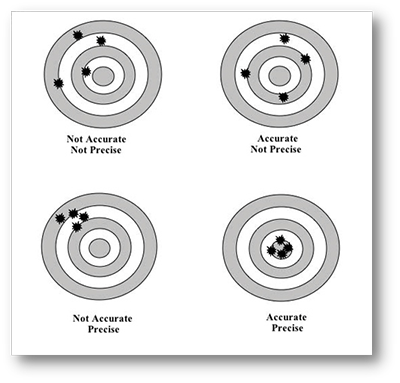
Consider a dartboard to help you understand this. Precision is when all the darts land in the same location, notwithstanding their distance from the bullseye. Though it's just one throw, accuracy is when the dart lands on the bullseye.

Excellent accuracy and precision combined with a CNC machine will help to lower material waste, increase efficiency, and satisfy the most exacting standards. That is vital in aerospace, automotive, and electronics sectors where every component must satisfy exact criteria. It Equipped with both features, a machine guarantees consistent, high-performance output.

Why Does Machining Precision Matter?

Machining requires precision for various reasons. Repeatability is among the main advantages of accuracy. In sectors like automotive or aerospace, each item must be the same even though parts are manufactured in great numbers. CNC machines guarantee that independent of production volume, every single component satisfies the same criteria thanks to their great precision.

These are the main causes of the great importance of accuracy:

· Consistency in Mass Production: A small variation can cause quality control problems throughout thousands of parts. For instance, a part may not operate as intended when assembled if it is routinely cut somewhat too small. Precision guarantees that every component is produced according to the same criteria, solving this issue.

· Reduced Material Waste: Precision machines effectively use materials, reducing waste. Any machining process flaw, no matter how little, can cause material to be modified or discarded. Along with costing more, this wastes priceless resources.

· Higher Quality Products: High precision guarantees that parts are created exactly as needed in sectors where safety and dependability rule, including medical equipment or aerospace. A product failure arising from even small differences may have disastrous results.

· Less Need for Adjustments: Precision lessens the demand for rework or corrections. Precisely produced pieces fit together, saving the need for further adjustments following machining.


In What Ways Could Accuracy Affect Machined Part Quality?

Precision guarantees repeatability; accuracy guarantees that items satisfy the intended standards. Accuracy is crucial for manufacturing important components—such as those found in medical equipment, electronics, or heavy machinery.

For instance, every flaw in a component you are machining for a high-performance engine can cause mechanical breakdown. The engine components must mesh precisely. A small difference can lead to friction, heat, and wear, degrading engine performance and lifetime. Accurate machining guarantees that every component fits together as it should.

Key Effects of Machining Accuracy:

· Meeting Tight Tolerances: Certain sectors demand items produced under very limited tolerances. Reaching these criteria depends on accurate machines. No matter how exact, inaccurate equipment can fail to reach these important tolerances and produce defective items.

· Assembly and Functionality: Accurate machining of components will result in proper fit and desired functionality. Accuracy guarantees that the product will function as intended, whether you are building a basic assembly line or a sophisticated aeronautical component.

· Improving Reliability: In sectors including medical equipment, even the smallest mistake can make all the difference between life and death. Reliable and precise operation of parts is guaranteed by accurate machining.


Accuracy vs. Precision Examples

Evaluating the performance of manufacturing activities depends much on accuracy and precision, which are independent factors. While precision indicates the machine's capacity to perform the same operation regularly, accuracy in CNC machining gauges a part's relative proximity to its intended dimensions. In order to keep specified dimensions, most CNC machines depend on computer software. Still, the outcomes may differ:

· Precise and Accurate: A CNC machine constantly generates parts with minimum errors that match the design criteria. One gets accuracy as well as precision.

· Accurate but Not Precise: Though the machine generates pieces almost within the specified measurements, the outcomes vary. While some components stray, others satisfy the criteria.

· Precise but Not Accurate: Although the machine always generates parts with the same measurements, those measurements deviate from the desired specifications. Though wrong, the parts are similar.

· Neither Precise Nor Accurate: The machine generates inconsistent pieces; none satisfy the needed standards.

Differentiating between accuracy and precision and independently measuring them will help to guarantee a high-quality machining operation. Examples illustrating how these two factors influence part machining are below:

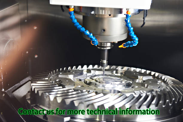
1. Precision and Accuracy in Gear Manufacturing: Precision and accuracy define a CNC machine that generates gears with the right size and form for seamless operation. The machine is accurate but not exact; if the gears vary in size, they still fit appropriately.

2. Medical Device Production Accuracy: Medical equipment has high criteria. Though accuracy may be insufficient if some pieces vary, machine-produced parts with exact implant specifications could be accurate.

Knowing these differences optimizes the machining process, guaranteeing accuracy and precision for dependable, high-performance products.

Could A Machine Be Precise But Not Accurate?

A machine can be precise but not accurate at the same time indeed. In machining, this is a vital difference.

Suppose you are making cylindrical pieces on a lathe. The machine is exact since it generates the same output every time if it constantly generates pieces that are 0.5 millimeters bigger than the target diameter. The parts are not the right size; hence, they are not accurate either. That emphasizes how to separate traits—accuracy and precision—that must be optimized and call for separate optimization.

A machine can produce consistent components even if it is not accurate if it is exact; those parts will not satisfy the required criteria nevertheless. That can be a challenge in sectors like aerospace or automotive, where the pieces must precisely fit one another.

Key Differences:

· Precision: Always leads to the same outcome, even if it's wrong.

· Accuracy: generates the right outcome despite an erratic process.

Should a machine prove accurate but not exact, calibration could be necessary to fix the inaccuracy. Recalibrating the equipment can change the process to become exact and accurate.

Why Would A Machine Be Precise But Not Accurate?

Wear and tear, poor calibration, or incorrect setup can cause machines to grow imprecise or inaccurate. Even the best devices could need recalibration over time to keep accuracy and precision. Therefore, regular maintenance and calibration are essential to guarantee that devices satisfy the required criteria.

Although CNC Yangsen's machines are made to keep accuracy and precision throughout time, regular calibration helps to guarantee long-term performance.


How Do Machining Tolerances Affect Precision and Accuracy?

In machining, tolerances are deviations allowed from a given dimension. Tolerances allow a margin for slight deviations since no machine can generate precisely to specification every time.

Most machining processes find that the cost of output increases with decreasing tolerance. Tolerances are intimately connected to both accuracy and precision. Precise and accurate machines can generate parts regularly falling inside the necessary tolerance range.

Types of Tolerances:

· Tight Tolerances: These are applied even when the tiniest departure from the designated measurement could lead to issues. For an aviation engine, for instance, parts might have to be machined within a tolerance of 0.01 millimeters since even the tiniest change might compromise performance.

· Loose Tolerances: Looser tolerances can be employed in some areas where accuracy is unnecessary. For non-critical parts that won't be under stress or wear, for instance, looser tolerances allow for small variations from the intended size or form.

Machines such as the very precise CNC verticle machine centers offered by CNC Yangsen are perfect for exact tolerances. They guarantee that every part satisfies the necessary criteria by operating within quite small margins of error.


How Can You Make Machining Both Precise And Accurate?

High-quality parts require the proper mix of accuracy and precision. A precise but not accurate machine will regularly generate parts that are off. On the other hand, if a machine is accurate but not exact, it will only seldom generate parts that satisfy the criteria.

· Invest in High-Quality Machinery: Not every machine is built equal. While certain devices can offer accuracy and precision, others may be made for only one. CNC Yangsen's high-end machines provide accuracy and precision, guaranteeing constant outcomes.

· Maintain Equipment: Regular maintenance is even required of the most sophisticated machinery. Keeping machines both accurate and exact depends on proper maintenance, part replacement, and recalibration.

· Calibration: Frequent calibration guarantees machines' correctness throughout. Even the greatest machines can wander from their intended specs without calibration, producing inaccurate products.


Complex Machining Requires Precision And Accuracy, Why?

Ensuring that items satisfy the required criteria in complicated machining projects requires accuracy and precision. Complex jobs often call for a machine capable of preserving accuracy and precision throughout the process, including several processes, tight tolerances, and using several materials.

For instance, think of the manufacturing of an aircraft multi-part assembly. The whole assembly may suffer if one component is inaccurately or precisely lacking. In these situations, even little variations from the planned design can cause performance problems, safety hazards, or failure of the ultimate result.

For complex machining jobs, machines such as the 5-axis CNC machining centers from CNC Yangsen are perfect since they provide both accuracy and precision even when working with challenging materials or intricate geometries.

Complex Machining Applications Of Accuracy And Precision:

· Aerospace Components: High-precision machining guarantees that, under the worst conditions, all parts fit together exactly.

· Medical Devices: Errors in medical equipment can endanger people. Precision machining ensures the intended functionality of devices.

High-precision tools for these jobs would be CNC machining centers from CNC Yangsen. Designed to satisfy the strict criteria of various sectors, they provide accuracy and precision for the most important jobs.


How Do Precision and Accuracy Impact Efficiency and Cost?

Machining processes' cost and efficiency directly rely on accuracy and precision. Precise and accurate machines lower rework, reduce waste and boost production speed. Over time, this translates into notable cost reductions.

Accurate and exact machining of parts reduces the necessity of remakes or corrections. Because every part is created to exact standards, accurate machines help cut the time spent on quality control inspections.

Benefits of High-Precision and Accurate Machines:

· Reduced Waste: Consistent machine performance reduces waste of materials.

· Lower Rework Costs: Less time and money spent fixing mistakes equals fewer mistakes overall.

· Increased Production Speed: Faster and more dependably produced parts by precision machines raise general efficiency.

By providing unsurpassed precision and accuracy, lowering waste, and enhancing production efficiency, machines such as high-precision CNC turning centres help firms save time and money.


How to Improve Machining Precision and Accuracy?

Minimizing waste and manufacturing high-quality products depend on improved machining precision and accuracy. These are several strategies to get better:

· Regular Calibration: Machines are periodically calibrated to guarantee their operation within the intended tolerances.

· Use High-Quality Tools: Purchasing sharp, long-lasting cutting tools guarantees constant results and improved accuracy.

· Minimize Tool Wear: Changing tired tools immediately helps avoid machining process mistakes.

· Maintain Optimal Speeds: Correct feed rates and spindle speeds running machines guarantee accurate and precise components.

· Perform Routine Maintenance: Frequent maintenance and cleaning of machines helps to prevent mechanical problems generating mistakes.

· Stable Environment: Temperature swings and vibrations can affect accuracy; a controlled atmosphere reduces these influences.

Machining accuracy and precision will be much improved by applying these techniques.


Conclusion:

Producing high-quality products that meet industrial machining standards depends on accuracy and precision. Accuracy ensures that each component is produced to the appropriate standard, while precision ensures repeatability. For industries that require exacting standards, advanced CNC machines offer an ideal combination of both, making them absolutely indispensable.

Manufacturers can increase general product quality, lower waste, and achieve higher efficiency by choosing the correct equipment. If you want to improve your machining techniques, consider selecting CNC machines that are accessible at CNC Yangsen.

Choosing Between Direct Connected Spindle and Belt Type Spindle!

Introduction

Choosing Between Direct Connected Spindle and Belt Type Spindle! This blog analyses core disparities. Performance and maintenance features are discussed.

As for the DCS and the BTS, the two come with their own pros. Find out which spindle is fit for you. Performance of your machine depends on this choice that you make. Stay tuned for comprehensive studies.


What Are the Core Differences Between Direct Connected and Belt Type Spindles?

· Operational Mechanisms

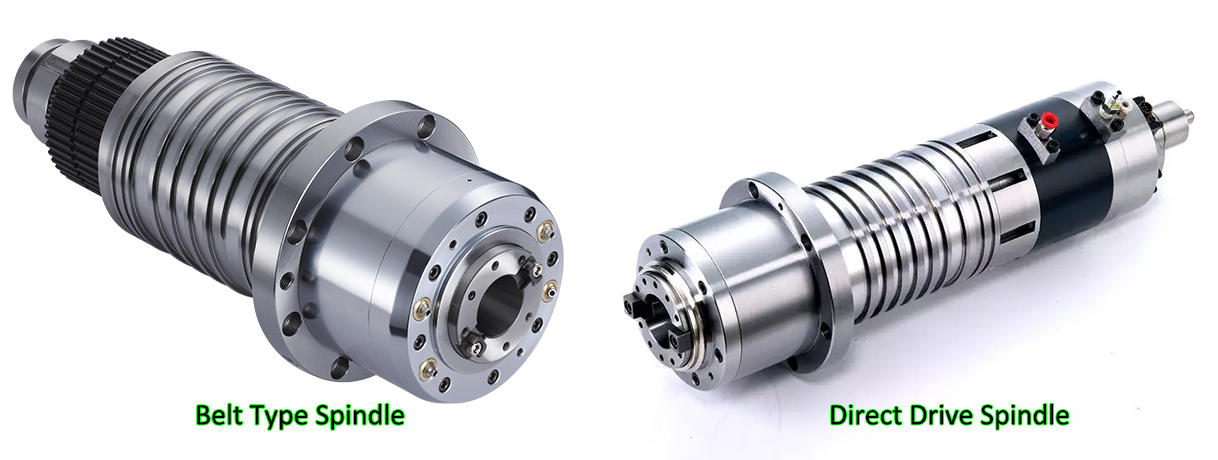
The direct connected spindle has a motor shaft connected directly to the spindle shaft.

This setup ensures minimal vibration. In a belt type spindle power transmission is achieved using a belt drive which is based on pulleys and belts.

Models with direct connection provide high precision with fewer moving parts. Belt type is a versatile option that comes with different pulley ratios. Both are suitable for specific applications in machining.

· Speed Control

The uniform speed of the spindles comes from the direct motor-shaft linkage. These spindles allow the machines to operate at high speed. The variable pulley diameters used in this type of spindles play an important role in speed adjustment, making them more flexible.

The speed stability of these systems is affected by the belt tension. Directly connected systems attain constant speeds flawlessly. The two spindles were intended to handle different machining.

· Torque Transmission

A straight connected countershaft transmits the torque right from the motor reducing power losses. These spindles ensure consistent torque. Belt spindles transmit torque through belts and pulleys, with a risk of slippage. Torque consistency can have issues of belt wear.

Direct connected systems make sure prompt torque transfer. Both have specific advantages depending on the application.

· Cost Efficiency

The issue with the direct connected spindles is that they are more expensive for their complicated design at first. Maintenance is usually less often. Belt type spindles are inexpensive to begin with, and their components are easier to change also.

These spindles might demand more frequent maintenance. Indirect systems are cheaper but less stable. Such devices regulate budgeting between performance and specific purposes.


How Do Direct Connected Spindles Enhance Machine Performance?

· Precision Levels

Precise direct connected spindles (DCS) decrease backlash to achieve higher levels of accuracy. They achieve ±0.001mm accuracy. The run out of BTS (belt type spindles) is greater than that of MLT. DCS employ high quality servo motors with rotational speed exceeding 10,000 rpm.

Pulley and belt are the resources the band BTS leverages. During DCS, the shaft alignment is made meticulously. BTS can experience misalignment.

An advanced feedback loop of the encoder is provided by DCS. Positioning BTS has limited accuracy. DCS systems mitigate thermal contraction and expansions effects. BTS belts, unfortunately, begin wearing out over time. The DCS ensures a better pose fix.

BTS introduces vibration. DCS provides improved repeatability. BTS requires frequent maintenance. A DCS is ideally for super precise jobs. BTS struggles with micro-movements. A DCS integrated system leads to repeatable machining results.

· Efficiency Boost

DCS, the direct connected spindles, make manufacturing process efficient in a way that the pin is closer to the ground. They use high-powered servo motors that are high in efficiency.

Spindles in Belt type (BTS) are susceptible to energy wastage through belts. DCS has direct power transmission which means that there is no signal loss from changes in voltage and current. BTS involves mechanical friction. DCS is functionally characterized by shorter response time.

BTS problem is caused by the mistimed torque transmission. DCS monitoring specifies constant rpm. BTS systems have tensions which are adjusted for some belts whereas for others tensions do not change.

DCS creates less maintenance outage, in contrast. BTS needs belt replacement on a regular basis since this part is constantly in contact with the wheel. DCS supports continuous operation.

BTS experiences slippage issues. DCS provides the most sophisticated cooling system. BTS has bad cooling performance. DCS maximizes power utilization. BTS operates less efficiently.

· Speed Variability

The direct resistance connected spindles (DRCS) have the advantage of speed variability. They are responsible for changing rpm dynamically. Belt type spindles (BTS) have small velocity ranges because of their design. DCS, on the other hand, employs VFD.

BTS works with transmission ratio fixed and the ratio is constant. DCS can regulate the rpm operation and the range is from low to high. The speed shifter in BTS will require manual attentiveness.

One virtue of DCS is its smoothness during the switching. The speed consistency is the major negative accompanying the BTS. DCS systems basically play a role in adaptive speed control.

Due to its mechanical limitation, BTS is subjected. DCS allows for quick generation speed changes, thus decreasing downtime associated with speed changes. It calls for several stopovers to rectify alignment.

ATC improves the accuracy between different cruise speeds. BTS lacks flexibility. The DCS is flexible enough to adjust to different raw material characteristics.

· Torque Consistency

The direct connected spindles called the Direct Connected Spindles (DCS) transmit torque output steadily. These robots feature servo-driven actuators with advanced precision.

Belt-type spindles (BTS) correspond with these torque fluctuations. DCS has constant torque throttle all through rpm range. At speeds over 80 miles per hour, the vehicle will encounter torque drops.

DCS better when it comes to the notion of load adjustment. Expansion of the belt is a direct influence on BTS. DCS systems include the feedback loops too.

There is a shortfall in the immediate generation control for BTS. DCS is declared accurate with respect to the torque. BTS structures have embedded slippage problems. DCS supports heavy-duty machining.

BTS is designed for maximum torque and acceleration. DCS minimizes mechanical wear. BTS system should be improved continually. The DCS eliminates the pulsing by providing the appropriate torque smooth delivery.

· Operational Stability

While direct connected spindles (DCS) create operation stability, they also guarantee grinding operations uninterrupted. They help to be anti-vibration, low in noise.

BTS type spindles (BTS) are vibration producing to the level of being dangerous. DCS is using the balanced structure motor. The ski lift mechanism in BTS is improperly designed, causing imbalances.

DCS provides consistent performance. DCS provides damper technology to avoid the negative effects of un-damped vibration modes. The BTS does not incorporate an advanced vibrational control mechanism. DCS enhances cutting quality. BTS compromises surface finish.

DCS supports high-speed machining. BTS limits operational speeds. DCS ensures long-term reliability. BTS has to exchange part instrumental frequently. DCS minimizes unplanned downtimes.

BTS involves more maintenance. DCS systems ensure the structural integrity of all affected structures.

Criteria

Direct Connected Spindles

Belt Type Spindles

Precision Levels

High precision (±0.001 mm)

Moderate precision (±0.01 mm)

Efficiency Boost

Higher efficiency (90%+)

Lower efficiency (70-80%)

Speed Variability

Wide range (500-40,000 RPM)

Limited range (500-10,000 RPM)

Torque Consistency

Consistent torque delivery

Variable torque

Operational Stability

High stability, less vibration

Moderate stability, more vibration

Table on How Do Direct Connected Spindles Enhance Machine Performance!


What Advantages Do Belt Type Spindles Offer in Industrial Settings?

· Cost Savings

The type of spindle with a belt (BTS) reduces initial investment costs. They have cheap pulleys systems. Higher motor costs are associated with the direct connected spindles.

BTS offers cost-effective maintenance. DCS requires expensive components. BTS has very basic mechanical parts. DCS requires the creation of tailor-made servo motors.

BTS systems decrease operating expenses. DCS increases maintenance costs. BTS offers a low cost alternative to erecting pylons and transmission lines. DCS employs expensive direct drive machines. BTS is the advantage of small manufacturers having low-cost.

· Flexibility Increase

Another advantage of Belt type spindles (BTS) is their versatility in speed control. They adjust the pulley size. Direct connected spindles (DCS) have predetermined speed ranges.

BTS allows easy accelerations. DCS needs complex programming. BTS systems became suitable for various machining operations. DCS lacks this flexibility.

BTS is particularly adaptable for processing a wide variety of materials. DCS is less adaptable. BTS enables easy customization. DCS has limited adjustability. BTS enhances operational versatility.

· Maintenance Ease

Belt-type spindles (BTS) develop ease of repair and maintenance. They replace the belts without any trouble. Spindles which are directly linked (DCS) have to use specially designed pieces of equipment. BTS systems require schedule disrupted as little as possible.

DCS involves complex repairs. BTS is designed for simple belt changes. DCS necessitates motor recalibrations. BTS components can be easily bought everywhere.

DCS parts are especially rare. BTS reduces service intervals. DCS demands frequent check-ups. BTS ensures straightforward troubleshooting.

· Environmental Suitability

BTS spindles operate well in severe conditions. They put up with dust and dirt. Direct connected spindles (DCS) require environment with lower discharges. BTS systems mediate temperature changes.

DCS experiences thermal variation problems. BTS uses the components that are resistant to mechanical stresses. DCS requires sensitive electronics.

BTS is reliable for industrial environments and networks. DCS suits controlled environments. BTS stands for avoiding interruptions in factory operation. DCS is more delicate. BTS makes the best of it in adverse conditions.


When Should You Choose a Direct Connected Spindle Over a Belt Type Spindle?

· High Precision

Where more precision is required, use direct connected spindles (DCS). DCS achieves ±0.001 mm accuracy. More run-out for the belt type spindles (BTS) is also observed. DCS uses high-resolution encoders. Lack of precise BTS systems limits its effectiveness.

DCS is capable of mitigating thermally induced shrinkage. BTS experiences thermal drift. DCS assembles the stable shaft alignment. Over time the angle of BTS will deviate. DCS ensures consistent accuracy. BTS struggles with micro-movements. DCS boasts on high precision tasks.

· Enhanced Durability

Choose DCS for excellent durability. DCS is equipped with the servo motors of the highest performance. Belt drive spindles (BDS) are belted and hence risky. DCS components are in accordance with the high loads. BTS parts wear quickly. DCS offers advanced cooling systems.

BTS heat is not efficiently controlled. The DCS systems require low maintenance. BTS involves belt replacement frequently. DCS ensures long-term reliability. BTS involves regular servicing. DCS provides superior longevity. BTS components degrade faster.

· Optimal Speed

Opt for DCS option for highest speed attainment. DCS incorporates the use of variable-frequency drives. Fixed pulleys create spindles with belt type (BTS). DCS provides a modified curve of rpm settings.

BTS offers various manual speed adjustments. CNC systems, however, are capable of high-speed machining. BTS still has the bottleneck problem.

DCS provides rapid acceleration. BTS experiences unavoidable speed transition sluggishness. DCS ensures a steady speed during drifts. BTS cars have speed irregularities. DCS enhances machining efficiency.

· Superior Torque

Selecting direct drive spindles (DCS) will provide the highest torque. DCS is characterized by providing constant torsion. Belt type spindles (BTS) are torque-variation sensitive. DCS facilitates constant torque throughout the rpm range. The far torque of BTS is attenuated when speed is higher.

DCS uses precision-engineered motors. BTS is subject to the pulling strength. DCS supports heavy-duty machining. BTS faces the problem of relative high-torque.

The DCS control systems use real time torque control. BTS lacks such precision. DCS delivers careful linear torque. BTS experiences slippage.

· Critical Applications

In regard to critical functions, opt for direct connected spindles (DCS). DCS ensures precise performance. The belt-type spindles (BTS) are not dependable. DCS supports high-precision tasks.

BTS struggles with accuracy. DCS maintains stable operation. BTS experiences frequent misalignment. DCS systems have more elaborate feedback cycles. BTS lacks real-time monitoring.

DCS is particularly notable in critical surroundings. BTS falters under stress. DCS provides consistent results. BTS requires constant adjustments. Exactness is a DCS benefit while being used for crucial machining.

Criteria

Direct Connected Spindles

Belt Type Spindles

High Precision

Required (±0.001 mm)

Not critical (±0.01 mm)

Enhanced Durability

Long lifespan, low maintenance

Shorter lifespan, higher maintenance

Optimal Speed

Necessary for high-speed operations

Sufficient for lower speed needs

Superior Torque

Essential for heavy-duty tasks

Acceptable for light tasks

Table on When Should You Choose a Direct Connected Spindle Over a Belt Type Spindle!


What Are the Maintenance Implications for Each Type of Spindle?

· Routine Checks

Directly connected spindles (DCS) are always thoroughly visually examined. Such procedures include motor inspection and encoder calibration. The belt type spindles (BTS) require for belt tightening. DCS systems require sensor alignment to be operated regularly. In BTS, pulley wears need to be inspected.

DCS check-ups relates to thermal management. BTS inspection is to ensure the belt is not damaged. DCS requires vibration monitoring. BTS needs to be frequently replaced as the belt wears out.

DCS makes use of modern diagnostics. BTS prefers faster checking techniques. DCS ensures long-term accuracy.

· Lubrication Needs

Spindles connected via direct current (DCS) have very few lubrication requirements. They use sealed bearings. Belt-type spindles (BTS) require periodic belt lubrication. DCS systems utilize auto lubricating parts. BTS requires periodic oiling. DCS operates with an advanced grease removal system.

BTS demands manual lubrication. DCS enhances the grease life performance. BTS lubrication significantly impacts belt life. DCS uses high-efficiency lubricants.

BTS employs standard oils. DCS reduces maintenance intervals. BTS requires regular inspection of its lubrication.

· Component Wear

Direct connected spindles (DCS) do not wear out components easily. They use precision-engineered parts. Belt type spindles (BTS) are a common cause of belt wear.

DCS systems contain rugged bearings. The BTS incorporates the replacement belts. DCS lowers wear down by means of the direct drive system. BTS has disadvantage of belt stretch.

DCS is made of hardened steel shafts. BTS uses rubber belts. DCS reduces maintenance costs. BTS usually entails frequent parts replacing. DCS contributes to longer part life.

· Operational Lifespan

Unlike other connected spindles, direct connected spindles (DCS) have a longer usable lifespan. They are servo motor-based. Belt type spindles (BTS) have shorter lifetimes.

DCS systems use resistant components. BTS parts wear quickly. DCS is thus superior to the traditional convection ovens since it is more efficient in thermal management.

BTS lacks efficient cooling. DCS stays performance over the time. BTS experiences gradual degradation. DCS need a lesser number of repairs. BTS involves regular maintenance. DCS offers consistent operation.


Conclusion

Selecting between Direct Connected Spindle and Belt Type Spindle! We discussed the issues of accuracy, quickness, and long-term survival. DCS ensures accuracy and durability that other devices do not. BTS can help to cut cost and increase flexibility. Maintenance needs vary significantly.

Each spindle type has tailored specific benefits. Your choice affects the general quality of the machine's performance. Consider all factors carefully. Visit CNCYANGSEN for expert advice. Choose your spindle right by today!


FAQs!

Q: Why Should You Choose Direct Connected Spindle For High-Precision Tasks?

A: Direct Connected Spindles (DCS) has an outstanding performance in accuracy and error is controlled within ±0.001mm precision. They prevent cold chilling and thermal expansion, resulting into high level of accuracy thus making them suitable for every precision machining job.

Q: How Does Maintenance Differ Between Direct Connected Spindle And Belt Type Spindle?

A: Direct-connected spindles (DCS) have an advanced diagnostic system that does not need an express maintenance. Belt-type spindle (BTS) requires a more frequent upkeep which includes regular belt replacement and lubrication.

Q: Which Spindle Type Offers Better Durability In Harsh Environments?

A: DCS operates very well in terms of the toughness thanks to the utilization of advanced materials and sealing bearings. The belt type spindles (BTS) maintain high efficiency but due to belt wear constraints, their operating life is relatively short.

Q: How Do Operational Loads Affect Direct Connected Spindle And Belt Type Spindle?

A: In direct connected spindles (DCS) high-torque servo motors are capable of processing dynamic loads with uniform torque. Silent or Hi-torque spindles (BTS) are not effective under high loads and vary most. 

A Complete Guide To CNC Milling Curved Surfaces

CNC milling, or Computer Numerical Control milling, is a machining process that uses computerized controls to precisely cut and shape materials into complex parts. This technology is essential in modern manufacturing due to its ability to produce intricate and accurate components efficiently, widely utilized in industries like aerospace, automotive, and medical.

Milling curved surfaces is more challenging than flat or straight-edge milling. Curved surfaces require special techniques and careful planning to achieve the desired contours and finishes. These surfaces are commonly found in advanced components such as turbine blades, automotive parts, and medical implants.

This article focuses on the specific challenges and techniques of CNC milling curved surfaces. It aims to provide practical insights and detailed information to help you master the milling of curved surfaces, enhancing your ability to produce precise and high-quality parts.


Basics Of CNC Milling

What Is CNC Milling?

CNC milling, or Computer Numerical Control milling, is a machining process where computerized controls direct cutting tools to shape materials into precise components. This process evolved from manual milling, where machinists operated milling machines by hand. With the advent of CNC technology in the 1960s and 1970s, milling machines became automated, significantly increasing the precision, efficiency, and complexity of parts that could be produced.

Key components of CNC milling machines include the CNC controller, which interprets the digital instructions; the spindle, which holds and rotates the cutting tool; and the worktable, where the material is secured. Additional components such as cooling systems, tool changers, and enclosures enhance the machine's functionality and performance.

Types of CNC Milling Machines

There are several types of CNC milling machines, each suited for different applications:

● Vertical Milling Machines: These machines have a vertically oriented spindle, which moves up and down. They are ideal for flat surfaces and simple geometries.

● Horizontal Milling Machines: These machines have a horizontally oriented spindle, which allows for the milling of heavier and more complex workpieces. They are often used for cutting slots and grooves.

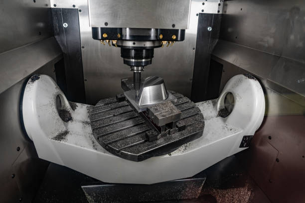
● Multi-axis CNC Machines: These advanced machines can move the spindle and workpiece in multiple axes (typically 3 to 5 axes), allowing for the creation of intricate and complex parts with curved surfaces.

Fundamental Milling Operations

Several fundamental milling operations are essential for various applications:

● Face Milling: Involves cutting a flat surface perpendicular to the spindle axis. It's used to create a smooth, flat finish on the top of the workpiece.

● Peripheral Milling: Also known as slab milling, this operation cuts along the edge of the workpiece with the axis of the cutting tool parallel to the surface being machined. It is used for producing long, straight cuts and contours.

● End Milling: Uses an end mill cutter to produce slots, pockets, and intricate contours. The cutting tool rotates on an axis perpendicular to the workpiece surface, allowing for precise cutting of complex shapes.


Curved Surfaces In Milling 

Types Of Curved Surfaces

In CNC milling, curved surfaces can be categorized into three main types:

● Concave Surfaces: These are inward-curving surfaces resembling a bowl or a hollow shape. Milling concave surfaces requires precise control to ensure smooth and accurate contours, often used in components like molds and turbine blades.

● Convex Surfaces: These are outward-curving surfaces similar to a dome or a bump. Achieving a consistent finish on convex surfaces can be challenging, but they are common in parts such as gear teeth and certain automotive components.

● Complex 3D Surfaces: These surfaces combine multiple curves and angles, creating intricate geometries. Examples include sculpted parts in aerospace and automotive industries, where both aesthetic and functional precision are crucial.

Common Applications of Curved Surface Milling

Curved surface milling is essential in various industries, contributing to the production of high-precision and high-performance components:

● Aerospace Components: Curved surfaces are prevalent in aerospace for parts like turbine blades, airfoils, and fuselage components. Precision milling ensures these parts meet strict aerodynamic and performance standards.

● Automotive Parts: From body panels to engine components, the automotive industry relies on curved surface milling to produce parts that are both functional and aesthetically pleasing.

● Medical Implants: Custom implants, such as hip joints and dental implants, often feature complex curved surfaces that must fit precisely within the human body. CNC milling ensures the necessary accuracy and biocompatibility.

● Consumer Electronics: The sleek and ergonomic designs of modern electronic devices, like smartphones and laptops, often incorporate curved surfaces. Milling allows for the production of these smooth, appealing contours.

Challenges in Milling Curved Surfaces

Milling curved surfaces presents several challenges that require careful consideration and advanced techniques:

● Toolpath Generation: Creating an effective toolpath for milling curved surfaces is complex. The toolpath must account for the curves' varying angles and depths to ensure consistent and accurate material removal.

● Surface Finish Quality: Achieving a high-quality surface finish on curved surfaces can be difficult due to the varying angles and the need for smooth transitions. Optimizing cutting parameters and using the right tools are crucial for a flawless finish.

● Tool Wear and Breakage: Milling curved surfaces can cause uneven wear on cutting tools due to the constant changes in contact angles and forces. This can lead to premature tool wear or breakage, affecting both quality and efficiency. Regular monitoring and appropriate tool selection are essential to mitigate these issues.


Tools and Software for CNC Milling Curved Surfaces

Cutting Tools

Selecting the right cutting tools is critical for successful CNC milling of curved surfaces. Each tool type has unique characteristics suited for specific applications:

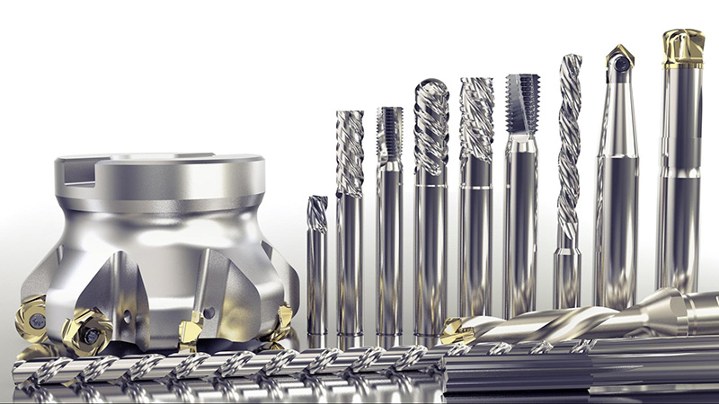
● Ball Nose End Mills: These tools have a hemispherical end, which makes them ideal for machining complex 3D contours and curved surfaces. The rounded tip reduces the risk of tool marks and ensures a smooth finish, making them perfect for intricate mold cavities, die shapes, and aerospace components.

● Bull Nose End Mills: Featuring a flat end with rounded corners, bull nose end mills are useful for both roughing and finishing operations. The rounded edges help in reducing stress concentrations, minimizing the likelihood of tool breakage when machining steep or deep curved surfaces.

● Tapered End Mills: Tapered end mills have a conical shape, which provides greater strength and rigidity, making them ideal for milling deep cavities and intricate details on curved surfaces. These tools are often used in mold making and other applications requiring precise and stable cutting.

Tool Material and Coatings

The choice of tool material and coatings plays a significant role in performance, tool life, and surface finish quality:

● High-Speed Steel (HSS): HSS tools are durable and tough, making them suitable for general-purpose milling. However, they wear out faster than carbide tools, especially when milling hard materials or high-speed operations.

● Carbide Tools: Carbide tools are harder and more wear-resistant than HSS, making them ideal for high-speed milling and machining hard materials. They maintain their cutting edge longer, ensuring consistent performance and better surface finishes.

● Coatings (TiN, TiCN, AlTiN): Applying coatings to cutting tools enhances their performance and longevity. Titanium Nitride (TiN) improves wear resistance and reduces friction. Titanium Carbo-Nitride (TiCN) offers better hardness and lubricity, ideal for harder materials. Aluminum Titanium Nitride (AlTiN) provides excellent thermal stability and wear resistance, making it suitable for high-speed and high-temperature applications.

CNC Software

Effective CNC milling of curved surfaces relies on advanced software for design, toolpath generation, and simulation:

● CAD Software (SolidWorks, AutoCAD): Computer-Aided Design (CAD) software is used to create detailed 3D models of the parts to be milled. SolidWorks and AutoCAD are popular CAD programs that allow designers to develop precise and complex geometries, which are essential for milling curved surfaces.

● CAM Software (Mastercam, Fusion 360): Computer-Aided Manufacturing (CAM) software translates CAD models into toolpaths that CNC machines follow. Mastercam and Fusion 360 are widely used CAM programs that provide advanced features for generating efficient and accurate toolpaths for curved surfaces, including adaptive clearing, contouring, and finishing strategies.

● Simulation Software: Before actual machining, simulation software helps visualize and optimize the milling process. It identifies potential issues like tool collisions and inefficient toolpaths. Integrated simulation features in CAM software, as well as standalone programs, are crucial for ensuring the milling process will proceed smoothly and without errors.

Process Planning for Curved Surface Milling

Design Considerations

Effective process planning for milling curved surfaces starts with careful design considerations:

● CAD Model Preparation: Preparing a detailed and accurate CAD model is the first step. The model should represent the final product with precise dimensions and features. Designers must ensure that all curved surfaces are well-defined and that the model includes any necessary fillets, radii, and transitions. High-resolution modeling helps avoid discrepancies during machining and ensures the toolpath generation is accurate.

● Surface Continuity and Smoothness: Maintaining surface continuity and smoothness in the CAD model is crucial for achieving a high-quality finish. Designers should use advanced CAD tools to check for and eliminate any discontinuities, sharp edges, or abrupt changes in curvature that could cause issues during machining. Smooth transitions between surfaces ensure that the milling process can produce a consistent and smooth finish.

Toolpath Strategies

Selecting the right toolpath strategy is essential for efficient and precise milling of curved surfaces:

● Parallel Milling: This strategy involves machining the surface in parallel passes, typically along a single axis. It is straightforward and effective for relatively simple curved surfaces. Parallel milling provides a uniform finish but may require additional passes for more complex geometries.

● Z-Level Milling: Also known as contour or waterline milling, this strategy involves milling the surface in horizontal layers or "slices" at different Z-levels. It is highly effective for complex 3D surfaces, allowing for precise control over the depth of cut and ensuring a consistent finish. Z-level milling is often used for finishing operations on intricate curved surfaces.

● 3+2 Axis Milling: This advanced strategy uses three linear axes and two rotational axes to orient the workpiece in the optimal position for each cut. It allows for more complex and efficient toolpaths, reducing the need for multiple setups and improving accuracy. 3+2 axis milling is ideal for parts with complex geometries and undercuts, providing greater flexibility and precision.


 Fixture and Workholding

Proper fixture and workholding methods are essential for stability and accuracy in milling:

● Clamping Methods: Visces and clamps are commonly used to secure the workpiece. Evenly distributed clamping force is crucial to prevent deformation, especially for delicate curved surfaces.

● Vacuum Fixtures: These use suction to hold the workpiece, ideal for thin or delicate parts. Vacuum fixtures provide uniform holding force and can be customized to fit the workpiece contours, ensuring stability and precision.

● Custom Jigs: Specifically designed for the workpiece, custom jigs offer tailored support and alignment. They are especially useful for complex or irregularly shaped parts, maintaining consistent and accurate machining.


Execution of Milling Curved Surfaces

Machine Setup

Before milling curved surfaces, proper machine setup is crucial to ensure accuracy and efficiency:

● Calibration and Alignment: Machines must be calibrated to ensure all axes are correctly aligned. This prevents errors in toolpath execution and ensures the dimensions of the milled part are accurate.

● Tool Setup and Offsets: Tools must be correctly installed and aligned with the spindle. Tool offsets are set to compensate for tool dimensions and ensure precise cutting depths and contours during machining.

Milling Parameters

Optimizing milling parameters is essential for achieving desired surface finishes and maintaining tool longevity:

● Spindle Speed: The rotational speed of the spindle affects cutting efficiency and tool life. Higher speeds are generally used for smaller tools and softer materials, while lower speeds are suitable for larger tools and harder materials.

● Feed Rate: Feed rate determines how quickly the cutting tool moves through the material. It impacts machining time, surface finish, and tool wear. Adjusting the feed rate optimally balances material removal rates with tool life and surface quality.

● Depth of Cut: The depth of cut refers to the thickness of material removed in each pass. It influences cutting forces, tool wear, and surface finish. Optimizing the depth of cut ensures efficient material removal without compromising part integrity or tool performance.


Conclusion

In a nutshell, CNC milling is integral to modern manufacturing, enabling precise fabrication of complex components essential across industries like aerospace, automotive, and medical fields.

Milling curved surfaces presents distinct challenges requiring specialized techniques and careful planning for achieving precise contours and optimal finishes. This article provides practical insights to enhance proficiency in CNC milling of curved surfaces, emphasizing the importance of advanced tools, software, and meticulous process optimization.


Frequently Asked Questions

What are the main challenges in CNC milling curved surfaces? 

● Achieving precise toolpaths

● Maintaining surface finish quality

● Managing tool wear.

Which tools are best for milling curved surfaces? 

Ball nose end mills for smooth finishes, bull nose end mills for roughing and finishing, and tapered end mills for deep cavities.

How do you achieve a high-quality surface finish on curved surfaces? 

Optimise cutting parameters like spindle speed, feed rate, and depth of cut, and use appropriate toolpath strategies.

What software is used for designing and programming CNC milling of curved surfaces? 

CAD software like SolidWorks and AutoCAD for design, and CAM software like Mastercam and Fusion 360 for toolpath generation.

Daily Maintenance Of CNC Machining Center

In order to better maintain various CNC machining center equipment, formulate appropriate inspection and maintenance specifications for different characteristics of each model, accurately implement daily maintenance, ensure the accuracy and stability of the equipment and extend the service life of the equipment, ensure safe production, avoid the occurrence of industrial accidents, and achieve the purpose of safety and efficiency. This document is specially formulated;

Scope: The daily inspection and maintenance operations of the CNC machining center equipment used are all specifications;

Daily maintenance: refers to the maintenance that CNC machine tool operators must perform every shift, mainly pre-shift and post-shift inspections to keep the equipment clean and check the condition of machine tool parts, lubrication conditions, and whether the screws are loose, etc.;


CNC Machine Daily Maintenance

1 The indicator lights on the operation panel are working properly and there are no abnormal alarms

2 Confirm that the air pressure gauge is within the range of (0.4-0.6MPa) and there is no air leakage in the air compression system

3 Confirm that there is no abnormal noise in the motor and moving parts

4 Wipe the operation panel with a dry cloth to keep the panel clean

5 Clean the cutting fluid filter and keep it clean, and confirm that there is no water leakage in the cutting fluid pipeline

6 Check whether the cutting fluid level is normal, and adjust it if it is not normal

7 At the end of each shift, rinse the debris and other debris in the machine to keep the inside of the machine clean

8 Confirm that the spindle cooling fan is working properly

9 Check the safety door function. It is normal for the machine to stop running when the protective door is opened during machine operation

10 Check the air pressure detection function. It is normal for the air pressure to be too low to alarm when the air source is turned off

11 Check the emergency stop function. It is normal for the machine to stop running immediately when the emergency stop button is pressed during machine operation

12 Check whether the auxiliary equipment of the machine is intact and clean

CNC Weekly Maintenance

1 Wipe the surface of the machine with a dry cloth to keep the appearance clean

2 Clean the cutting fluid tank and pipes to remove foreign matter and keep the pipes unobstructed

3 Clean the spindle end face, spindle taper hole and tool magazine and wipe them clean with a cloth

4 Remove moisture from the water collector of the three-point combination


CNC Monthly Maintenance

1 Add grease to the XYZ three-axis and tool change mechanism

2 Clean the cooling fan filter of the electric cabinet

3 Check whether there is water or oil in the electric control box, and clean it if there is

4 Use the manual function to make the XYZ three-axis move the entire distance and check for abnormal noise

5 Clean the spindle cooling fan

6 Check whether the anchor screws are firm, and adjust the level of loose and unstable equipment

7 Clean the appearance of the oil recovery device and the filter element, check whether it is working properly, the motor has no vibration noise, and the oil return pipe is unobstructed;

Equipment Regular Maintenance

Monthly: Check the three-axis motor and moving parts for abnormal noise; Check the machine tool parameters for abnormalities; Check whether the air pressure is within the range of (0.4-0.6MPa) for air leakage; Check whether the shield and exposed pipelines are damaged; Check whether the lubricating oil system is working properly and whether there is oil leakage; Check whether the safety device is damaged (door lock, emergency stop switch, etc.);

Quarterly: Clean and maintain the debris in the XY axis sheet metal; Clean the cutting fluid tank and foreign objects in the pipeline to keep the pipeline unobstructed; Clean and maintain the spindle cooling fan; Check whether there is water or oil in the electric control box, and clean it if there is; Check whether the exhaust fan of the electric control box is working properly; Clean the appearance of the oil recovery device and the filter element, and check whether it is working properly; Semi-annual : Check whether water or oil has entered the transformer, and whether the exhaust fan is working properly; check whether the anchor screws are firm; clean the spindle end face and taper hole, and wipe them clean with a cloth; clean the tool magazine and check whether the tool holder is damaged; check whether the fans of each driver are operating normally; whether the water pump and oil recovery machine motor have vibration noise;

Annual: Check whether the tool magazine spring and each screw bearing are worn; check whether the machine tool backup battery has power; back up the machine tool certification documents and parameters; check whether the spindle tension is within the normal range; check whether the main power terminal and each terminal in the electric control box are loose; check whether the machine tool geometric accuracy is within the normal range; perform annual equipment accuracy inspection according to the "CNC machining center accuracy inspection table";