Application of TCT Temperature Cycle Chamber in Optical Communication Industry

Application of TCT Temperature Cycle Chamber in Optical Communication Industry

The arrival of 5G makes people feel the rapid development of mobile Internet, and optical communication technology as an important basis has also been developed. At present, China has built the world's longest optical fiber network, and with the continuous advancement of 5G technology, optical communication technology will be more widely used. The development of optical communication technology not only allows people to enjoy faster network speed, but also brings more opportunities and challenges. For example, new applications such as cloud gaming, VR, and AR require more stable and high-speed networks, and optical communication technology can meet these needs. At the same time, optical communication technology has also brought more innovation opportunities, such as intelligent medical care, intelligent manufacturing and other fields, will use optical communication technology to achieve more efficient and accurate operation. But you know what? This amazing technology cannot be achieved without the credit of macro environmental test equipment, especially the TC temperature cycle test chamber, which is a rapid temperature change test chamber. This article introduces you to the optical communication product reliability test quality manager - rapid temperature change laboratory.

temperature cycle test chamber

First, let's talk briefly about optical communication. Some people also say that it is called optical communication, so they are two in the end is not a concept. In fact, they are two of the same concept. Optical communication is the use of optical signals for communication technology, and optical communication is based on optical communication, through optical devices such as optical fibers, optical cables to achieve data transmission. Optical communication technology is widely used, such as our daily use of fiber optic broadband, mobile phone optical sensors, optical measurement in aerospace and so on. It can be said that optical communication has become an important part of modern communication field. So why is optical communication so popular? In fact, it has many advantages, such as high-speed transmission, large bandwidth, low loss and so on.

Common optical communication products include: optical cable, fiber switch, fiber modem, etc., used to transmit and receive optical signals of optical fiber communication equipment; Temperature sensor, strain sensor, displacement sensor, etc., can measure various physical quantities in real time and other optical fiber sensors; Erbium-doped optical amplifier, erbium-doped ytterbium-doped optical amplifier, Raman amplifier, etc., used to expand the intensity of optical signals and other optical amplifiers; Helium-neon laser, diode laser, fiber laser, etc., are light sources in optical communication, used to produce high brightness, directional and coherent laser light and other lasers; Photodetectors, optical limiter, photodiodes, etc., for receiving optical signals and converting them into electrical signals and other optical receivers; Optical switches, optical modulators, programmable optical arrays, etc. are used to control and adjust optical signal transmission and routing and other optical controllers. Let's take mobile phones as an example and talk about the application of optical communication products on mobile phones:

1. Optical fiber: Optical fiber is generally used as a part of the communication line, due to its fast transmission speed, communication signals are not easily affected by external interference and other characteristics, has become an important part of mobile phone communication.

2. Photoelectric converter/optical module: photoelectric converter and optical module are devices that convert optical signals into electrical signals, and are also a very important part of mobile phone communication. In the era of high-speed communication such as 4G and 5G, the speed and performance of such equipment need to be continuously improved to meet the needs of fast and stable communication.

3. Camera module: In the mobile phone, the camera module generally includes CCD, CMOS, optical lens and other parts, and its quality and performance also have a significant impact on the quality of optical communication of the mobile phone.

4. Display: Mobile phone displays generally use OLED, AMOLED and other technologies, the principle of these technologies are related to optics, but also an important part of mobile phone optical communication.

5. Light sensor: Light sensor is mainly used in mobile phones for environmental light sensing, proximity sensing and gesture sensing, and is also an important mobile phone optical communication product.

It can be said that optical communication products fill all aspects of our life and work. However, the production and use environment of optical communication products is often changeable, such as high or low temperature weather environment when working outdoors, or the use of a long time will also encounter changes in thermal expansion and contraction. So how is the reliable use of these products achieved? That has to mention our protagonist today - rapid temperature change test chamber, also known as TC box in the optical communication industry. In order to ensure that optical communication products still work normally under various environmental conditions, it is necessary to carry out rapid temperature change tests on optical communication products. The rapid temperature change test chamber can simulate a variety of different temperature and humidity environments, and simulate instantaneous extreme environmental changes in the real world within a rapid range. So how is the rapid temperature change test chamber applied in the optical communication industry?

1. Optical module performance test: Optical module is a key component of optical communication, such as optical transceiver, optical amplifier, optical switch, etc. The rapid temperature change test chamber can simulate different temperature environments and test the performance of the optical module at different temperatures to evaluate its adaptability and reliability.

2. Reliability test of optical devices: optical devices include optical fibers, optical sensors, grating, photonic crystals, photodiodes, etc. The rapid temperature change test chamber can test the temperature change of these optical devices and evaluate their reliability and life based on the test results.

3. Optical communication system simulation test: The rapid temperature change test chamber can simulate various environmental conditions in the optical communication system, such as temperature, humidity, vibration, etc., to test the performance, reliability and stability of the entire system.

4. Technology research and development: The optical communication industry is a technology-intensive industry, which needs to constantly develop new technologies and new products. The rapid temperature change test chamber can be used to test the performance and reliability of new products, helping to accelerate the development and market of new products.

In summary, it can be seen that in the optical communication industry, the rapid temperature change test chamber is usually used to test the performance and reliability of optical modules and optical devices. Then when we use the rapid temperature change test chamber for testing, different optical communication products may require different standards. The following are rapid temperature change test standards for some common optical communication products:

1. Optical fiber: Common test standards There are common optical fiber rapid temperature change test standards are the following: IEC 61300-2-22: The standard defines the stability and durability test method of optical fiber components, section 4.3 of which specifies the thermal stability test method of optical fiber components, in the case of rapid temperature changes to the optical fiber components for measurement and evaluation. GR-326-CORE: This standard specifies reliability test requirements for fiber optic connectors and adapters, including thermal stability tests to assess the reliability of fiber optic connectors and adapters in temperature changing environments. GR-468-CORE: This standard defines the performance specifications and test methods for fiber optic connectors, including temperature cycle testing, accelerated aging testing, etc., to verify the reliability and stability of fiber optic connectors under various environmental conditions. ASTM F2181: This standard defines a method for fiber failure testing under high temperature and high humidity environmental conditions to evaluate the long-term durability of the fiber. And the above standards such as GB/T 2423.22-2012 are tested and evaluated for the reliability of optical fiber in rapid temperature changes or long-term high temperature and high humidity environments, which can help the majority of manufacturers to ensure the quality and reliability of optical fiber products.

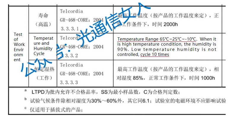
2. Photoelectric converter/optical module: The common rapid temperature change test standards are GB/T 2423.22-2012, GR-468-CORE, EIA/TIA-455-14 and IEEE 802.3. These standards mainly cover the test methods and specific implementation steps of photoelectric converters/optical modules, which can ensure the performance and reliability of products in different temperature environments. Among them, the GR-468-CORE standard is specifically for the reliability requirements of optical converters and optical modules, including temperature cycle test, wet heat test and other environmental tests, requiring optical converters and optical modules to maintain stable and reliable performance in long-term use.

3. Optical sensor: The common rapid temperature change test standards are GB/T 27726-2011, IEC 61300-2-43 and IEC 61300-2-6. These standards mainly cover the test methods and specific implementation steps of the temperature change test of the optical sensor, which can ensure the performance and reliability of the product in different temperature environments. Among them, the GB/T 27726-2011 standard is the standard for the performance test method of optical sensors in China, including the environmental test method of optical fiber sensors, which requires the optical sensor to maintain stable performance in a variety of working environments. IEC 60749-15 standard is the international standard for the temperature cycle test of electronic components, and it also has reference value for the rapid temperature change test of optical sensors.

4. Laser: Common rapid temperature change test standards are GB/T 2423.22-2012 "Electrical and electronic products environmental test Part 2: Test Nb: temperature cycle test", GB/T 2423.38-2002 "Basic test methods for electrical components Part 38: Temperature resistance test (IEC 60068-2-2), GB/T 13979-2009 "Laser product Performance test method", IEC 60825-1, IEC/TR 61282-10 and other standards mainly cover the laser temperature change test method and specific implementation steps. It can ensure the performance and reliability of products in different temperature environments. Among them, the GB/T 13979-2009 standard is the standard for the performance test method of laser products in China, including the environmental test method of the laser under temperature changes, requiring the laser to maintain stable performance in a variety of working environments. The IEC 60825-1 standard is a specification for the integrity of laser products, and there are also relevant provisions for the rapid temperature change test of lasers. In addition, the IEC/TR 61282-10 standard is one of the guidelines for the design of optical fiber communication systems, which includes methods for the environmental protection of lasers.

5. Optical controller: The common fast temperature change test standards are GR-1209-CORE and GR-1221-CORE. GR-1209-CORE is a reliability standard for optical fiber equipment, mainly for the reliability test of optical connections, and specifies the reliability experiment of optical connection systems. Among them, the rapid temperature cycle (FTC) is one of the test projects, which is to test the reliability of optical fiber modules under rapidly changing temperature conditions. During the test, the optical controller needs to perform temperature cycling in the range of -40 ° C to 85 ° C. During the temperature cycle, the module should maintain normal function and not produce abnormal output, and the test time is 100 temperature cycles. GR-1221-CORE is a reliability standard for fiber optic passive devices and is suitable for the testing of passive devices. Among them, the temperature cycle test is one of the test items, which also requires the optical controller to be tested in the range of -40 ° C to 85 ° C, and the test time is 100 cycles. Both of these standards specify the reliability test of the optical controller in the environment of temperature change, which can determine the stability and reliability of the optical controller under harsh environmental conditions.

In general, different rapid temperature change test standards may focus on different test parameters and test methods, it is recommended to choose the corresponding test standards according to the use of specific products.

Recently, when we discuss the reliability verification of optical modules, there is a contradictory indicator, the number of temperature cycles of optical module verification, there are 10 times, and 20 times, 100 times, or even 500 times.

Frequency definitions in two industry standards:

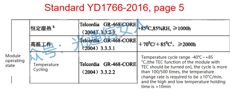
The references to these standards have clear sources and are correct.

For the 5G forward optical module, our opinion is that the number of cycles is 500, and the temperature is set at -40 °C ~85 °C

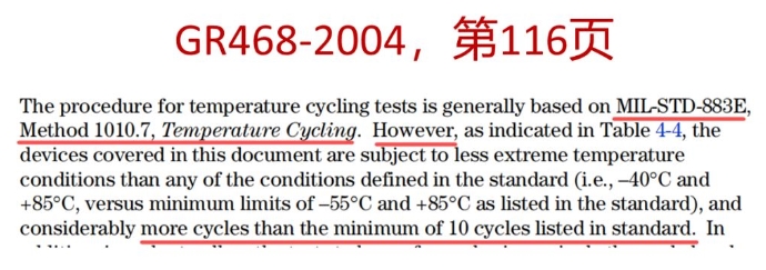
The following is the description of the 10/20/100/500 above in the original text of GR-468(2004)

Because of the limited space, this article introduces the use of rapid temperature change test chamber in the optical communication industry. If you have any questions when using rapid temperature change test chamber and other environmental test equipment, welcome to discuss with us and learn together.

IEC 60068-2

IEC 60068-2


Instructions:

IEC(International Electrotechnical Association) is the world's oldest non-governmental international electrical standardization organization, for the people's livelihood of the electronic products to develop relevant test specifications and methods, such as: mainframe board, notebook computers, tablets, smartphones, LCD screens, game consoles... The main spirit of its test is extended from IEC, the main representative of which is IEC60068-2, environmental test conditions its [environmental test] refers to the sample exposed to natural and artificial environments, but the performance of its actual use, transportation and storage conditions are evaluated. The environmental test of the sample can be uniform and linear through the use of standardized standards. Environmental testing can simulate whether the product can adapt to environmental changes (temperature, humidity, vibration, temperature change, temperature shock, salt spray, dust) at different stages (storage, transport, use). And verify that the characteristics and quality of the product itself will not be affected by it, low temperature, high temperature, temperature impact can produce mechanical stress, this stress makes the test sample more sensitive to the subsequent test, impact, vibration can produce mechanical stress, this stress can make the sample immediately damaged, air pressure, alternating humid heat, constant humid heat, corrosion application of these tests and can be continued thermal and mechanical stress test effects.

High and Low Temperature Test Chamber

Important IEC specification sharing:

IEC69968-2-1- Cold

Test purpose: To test the ability of automotive components, equipment or other component products to operate and store at low temperatures.

Test methods are divided into:

1.Aa: Temperature sudden change method for non-thermal specimens

2.Ab: Temperature gradient method for non-thermal specimens

3.Ad: Temperature gradient method of thermogenic specimen

Note:

Aa:

1. Static test (without power supply).

2. First cool down to the specified temperature of the specification before placing the test part.

3. After stability, the temperature difference of each point on the specimen does not exceed ±3℃.

4. After the test is completed, the specimen is placed under standard atmospheric pressure until the fog is completely removed: no voltage is added to the specimen during the transfer process.

5. Measure after returning to the original condition (at least 1hr).

Ab:

1. Static test (without power supply).

2. The specimen is placed in the cabinet at room temperature, and the temperature change of the cabinet temperature does not exceed 1℃ per minute.

3. The specimen shall be kept in the cabinet after the test, and the temperature change of the cabinet temperature shall not exceed 1℃ per minute to return to the standard atmospheric pressure; The specimen should not be charged during temperature change.

4. Measure after returning to the original condition (at least 1hr). (The difference between the temperature and the air temperature is more than 5℃).

Ac:

1. Dynamic test (plus power supply) when the temperature of the specimen is stable after charging, the temperature of the specimen surface is the most hot spot.

2. The specimen is placed in the cabinet at room temperature, and the temperature change of the cabinet temperature does not exceed 1℃ per minute.

3. The specimen should be kept in the cabinet after the test, and the temperature change of the cabinet temperature should not exceed 1℃ per minute, and return to the standard atmospheric pressure; The specimen should not be charged during temperature change.

4. Measure after returning to the original condition (at least 1hr).

Test conditions:

1. Temperature :-65,-55,-40,-25,-10,-5,+5°C

2. Resident time :2/16/72/96 hours.

3. Temperature variation rate: no more than 1℃ per minute.

4. Tolerance error :+3°C.

Test setup:

1. Heat generating specimens should be placed in the center of the test cabinet and the wall of the cabinet > 15cm

Sample to specimen > 15cm test cabinet to test volume ratio > 5:1.

2. For heat-generating specimens, if air convection is used, the flow rate should be kept to a minimum.

3. The specimen should be unpacked, and the fixture should have the characteristics of high heat conduction.


IEC 60068-2-2- Dry heat

Test purpose: To test the ability of components, equipment or other component products to operate and store in high temperature environments.

The test method is:

1. Ba: Temperature sudden change method for non-thermal specimens

2.Bb: Temperature gradient method for non-thermal specimens

3.Bc: Temperature sudden change method for thermogenic specimens

4.Bd: Temperature gradient method for thermogenic specimens

Note:

Ba:

1. Static test (without power supply).

2. First cool down to the specified temperature of the specification before placing the test part.

3. After stability, the temperature difference of each point on the specimen does not exceed +5℃.

4. After the test is completed, place the specimen under standard atmospheric pressure and return to the original condition (at least 1hr).

Bb:

1. Static test (without power supply).

2. The specimen is placed in the cabinet at room temperature, and the temperature change of the cabinet temperature does not exceed 1℃ per minute, and the temperature is reduced to the temperature value specified in the specification.

3. The specimen shall be kept in the cabinet after the test, and the temperature change of the cabinet temperature shall not exceed 1℃ per minute to return to the standard atmospheric pressure; The specimen should not be charged during temperature change.

4. Measure after returning to the original condition (at least 1hr).

Bc:

1. Dynamic test (external power supply) When the temperature of the specimen is stable after charging, the difference between the temperature of the hottest spot on the surface of the specimen and the air temperature is more than 5℃.

2. Heat up to the specified temperature of the specification before placing the test part.

3. After stability, the temperature difference of each point on the specimen does not exceed +5℃.

4. After the test is completed, the specimen will be placed under the standard atmospheric pressure, and the measurement will be carried out after the original condition is returned (at least 1hr).

5. The average temperature of the decimal point on the plane of 0~50mm on the bottom surface of the specimen.

Bd:

1. Dynamic test (external power supply) when the temperature of the specimen is stable after charging, the temperature of the most hot spot on the surface of the specimen is more than 5°C different from the air temperature.

2. The specimen is placed in the cabinet at room temperature, and the temperature change of the cabinet temperature does not exceed 1℃ per minute, and rises to the specified temperature value.

3. Return to standard atmospheric pressure; The specimen should not be charged during temperature change.

4. Measure after returning to the original condition (at least 1hr).

Test conditions:

1. The temperature 1000,800,630,500,400,315,250,200,175,155,125,100,85,70,55,40,30 ℃.

1. Resident time: 2/16/72/96 hours.

2. Temperature variation rate: no more than 1℃ per minute. (Average in 5 minutes)

3. Tolerance error: tolerance of ±2℃ below 200℃. (200~1000℃ tolerance ±2%)


IEC 60068-2-2- Test method Ca: Steady damp heat

1. Test purpose:

The purpose of this test method is to determine the adaptability of components, equipment or other products to operation and storage at constant temperature and high relative humidity.

Step 2: Scope

This test method can be applied to both heat-dissipating and non-heat-dissipating specimens.

3. No limits

4. Test steps:

4.1 Specimens shall be inspected visually, electrically and mechanically in accordance with relevant specifications before testing.

4.2 The test specimen must be placed in the test cabinet in accordance with the relevant specifications. In order to avoid the formation of water droplets on the test specimen after it is placed in the cabinet, it is best to preheat the temperature of the test specimen to the temperature condition in the test cabinet in advance.

4.3 The specimen shall be insulated in accordance with the specified residence.

4.4 If specified in the relevant specifications, functional tests and measurements shall be performed during or after the test, and the functional tests shall be performed in accordance with the cycle required in the specifications, and the test pieces shall not be moved out of the test cabinet.

4.5 After the test, the specimen must be placed under standard atmospheric conditions for at least one hour and at most two hours to return to its original condition. Depending on the characteristics of the specimen or the different laboratory energy, the specimen can be removed or retained in the test cabinet to wait for recovery, if you want to remove the time to be as short as possible, preferably not more than five minutes, if maintained in the cabinet the humidity must be reduced to 73% to 77% R.H. within 30 minutes, while the temperature must also reach the laboratory temperature within 30 minutes +1℃ range.

5. Test conditions

5.1 Test temperature: The temperature in the test cabinet should be controlled within the range of 40+2°C.

5.2 Relative humidity: The humidity in the test cabinet should be controlled at 93(+2/-3)% R.H. Within the range.

5.3 Resident time: The resident time can be 4 days, 10 days, 21 days or 56 days.

5.4 Test tolerance: temperature tolerance is +2℃, error of packet content measurement, slow change of temperature and temperature difference in the temperature cabinet. However, in order to facilitate the maintenance of humidity within a certain range, the temperature of any two points in the test cabinet should be maintained within the minimum range as far as possible at any time. If the temperature difference exceeds 1 ° C, the humidity changes beyond the permissible range. Therefore, even short-term temperature changes may need to be controlled within 1 ° C.

6. Test setup

6.1 Temperature and humidity sensing devices must be installed in the test cabinet to monitor the temperature and humidity in the cabinet.

6.2 There shall be no condensation water droplets on the test specimen at the top or wall of the test cabinet.

6.3 The condensed water in the test cabinet must be discharged continuously and shall not be used again unless it is purified (re-purifed).

6.4 When the humidity in the test cabinet is achieved by spraying water into the test cabinet, the moisture resistance coefficient shall not be less than 500Ω.

7. Other

7.1 The temperature and humidity conditions in the test cabinet must be uniform and similar to those in the vicinity of the temperature and humidity sensor.

7.2 The temperature and humidity conditions in the test cabinet shall not be changed during the power-on or functional test of the specimen.

7.3 Precautions to be taken when removing moisture from the specimen surface shall be detailed in the relevant specifications.


IEC 68-2-14 Test method N: Temperature variation

1. Test purpose

The purpose of this test method is to determine the effect of the specimen on the environment of temperature change or continuous temperature change.

Step 2: Scope

This test method can be divided into:

Test method Na: Rapid temperature change within a specified time

Test method Nb: Temperature change at specified temperature variability

Test method Nc: Rapid temperature change by double liquid immersion method.

The first two items apply to components, equipment or other products, and the third item applies to glass-metal seals and similar products.

Step 3 Limit

This test method does not validate high or low temperature environmental effects, and if such conditions are to be validated, "IEC68-2-1 test Method A:" cold "or "IEC 60068-2-2 Test Method B: dry heat" should be used.

4. Test procedure

4.1 Test method Na:

Rapid temperature change in a specific time

4.1.1 Specimens shall be inspected visually, electrically and mechanically in accordance with relevant specifications before testing.

4.1.2 The specimen type shall be unpacked, unpowered and ready for use or other conditions specified in relevant specifications. The initial condition of the specimen was room temperature in the laboratory.

4.1.3 Adjust the temperature of the two temperature cabinets respectively to the specified high and low temperature conditions.

4.1.4 Place the specimen in the low-temperature cabinet and keep it warm according to the specified residence time.

4.1.5 Move the specimen into the high-temperature cabinet and keep it warm according to the specified residence time.

4.1.6 The transfer time of high and low temperature shall be subject to the test conditions.

4.1.7 Repeat the procedure of Steps 4.1.4 and 4.1.5 four times

4.1.8 After the test, the specimen should be placed under standard atmospheric conditions and kept for a certain time to make the specimen reach temperature stability. The response time shall refer to the relevant regulations.

4.1.9 After the test, the specimens shall be inspected visually, electrically and mechanically in accordance with relevant specifications.

4.2 Test method Nb:

Temperature change at a specific temperature variability

4.2.1 The specimens shall be inspected visually, electrically and mechanically in accordance with relevant specifications before testing.

4.2.2 Place the test piece in the temperature cabinet. The shape of the test piece should be unpacked, unpowered and ready for use or other conditions specified in relevant specifications. The initial condition of the specimen was room temperature in the laboratory.

The specimen can be made operational if required by the relevant specification.

4.2.3 The temperature of the cabinet shall be lowered to the prescribed low temperature condition, and the insulation shall be carried out according to the prescribed residence time

4.2.4 The temperature of the cabinet shall be raised to the specified high temperature condition, and heat preservation shall be carried out according to the specified residence time

4.2.5 The temperature variability of high and low temperature shall be subject to the test conditions.

4.2.6 Repeat the procedure in Steps 4.2.3 and 4.2.4:

Electrical and mechanical tests shall be performed during the test.

Record the time used for electrical and mechanical testing.

After the test, the specimen should be placed under standard atmospheric conditions and kept for a certain time to make the specimen reach the temperature stability recovery time referred to the relevant specifications.

After the test, the specimens shall be inspected visually, electrically and mechanically in accordance with the relevant specifications

5. Test conditions

Test conditions can be selected by the following appropriate temperature conditions and test time or in accordance with the relevant specifications,

5.1 Test method Na:

Rapid temperature change in a specific time

High temperature: 1000800630500400315250200175155125100,85,70,55,4030 ° C

Low temperature :-65,-55,-40,-25.-10.-5 °C

Humidity: Vapor content per cubic meter of air should be less than 20 grams (equivalent to 50% relative humidity at 35 ° C).

Residence time: The temperature adjustment time of the temperature cabinet can be 3 hours, 2 hours, 1 hour, 30 minutes or 10 minutes, if there is no provision, it is set to 3 hours. After the test piece is placed in the temperature cabinet, the temperature adjustment time cannot exceed one-tenth of the residence time. Transfer time: manual 2~3 minutes, automatic less than 30 seconds, small specimen less than 10 seconds.

Number of cycles :5 cycles.

Test tolerance: The tolerance of temperature below 200℃ is +2℃

The tolerance of the temperature between 250 and 1000C is +2% of the test temperature. If the size of the temperature cabinet cannot meet the above tolerance requirements, the tolerance can be relaxed: the tolerance of the temperature below 100 ° C is ±3 ° C, and the tolerance of the temperature between 100 and 200 ° C is ±5 ° C (the tolerance relaxation should be indicated in the report).

5.2 Test method Nb:

Temperature change at a specific temperature variability

High temperature: 1000800630500400315250200175155125100,85,70 55403 0 'C

Low temperature :-65,-55,-40,-25,-10,-5,5℃

Humidity: Vapor per cubic meter of air should be less than 20 grams (equivalent to 50% relative humidity at 35 ° C) Residence time: including rising and cooling time can be 3 hours, 2 hours, 1 hour, 30 minutes or 10 minutes, if there is no provision, set to 3 hours.

Temperature variability: The average temperature fluctuation of the temperature cabinet within 5 minutes is 1+0.2 ° C /min, 3+0.6 ° C /min, or 5+1 ° C /min.

Number of cycles :2 cycles.

Test tolerance: The tolerance of temperature below 200℃ is +2℃.

The tolerance of the temperature between 250 and 1000℃C is +2% of the test temperature. If the size of the temperature cabinet cannot meet the above tolerance requirements, the tolerance can be relaxed. The tolerance of the temperature below 100 ° C is +3 ° C. The temperature between 100 ° C and 200 ° C is +5 ° C. (The tolerance relaxation should be indicated in the report).

6. Test setup

6.1 Test method Na:

Rapid temperature change in a specific time

The difference between the inner wall temperature of the high and low temperature cabinets and the temperature test specifications shall not exceed 3% and 8%(shown in °K) respectively to avoid thermal radiation problems.

The thermogenic specimen should be placed in the center of the test cabinet as far as possible, and the distance between the specimen and the cabinet wall, the specimen and the specimen should be greater than 10 cm, and the ratio of the volume of the temperature cabinet and the specimen should be greater than 5:1.

6.2 Test method Nb:

Temperature change at a specific temperature variability

Specimens shall be inspected visually, electrically and mechanically in accordance with relevant specifications before testing.

The specimen shall be in unpacked, unpowered and ready for use condition or other conditions specified in relevant specifications. The initial condition of the specimen was room temperature in the laboratory.

Adjust the temperature of the two temperature cabinets respectively to the specified high and low temperature conditions

The specimen is placed in a low-temperature cabinet and kept warm according to the specified residence time

The specimen is placed in a high temperature cabinet and insulated according to the specified residence time.

The transfer time of high and low temperature shall be performed according to the test conditions.

Repeat the procedure of steps d and e four times.

After the test, the specimen should be placed under standard atmospheric conditions and kept for a certain time to make the specimen reach the temperature stability recovery time referred to the relevant specifications.

After the test, the specimens shall be inspected visually, electrically and mechanically in accordance with the relevant specifications

6.3 Test method NC:

Rapid temperature change of double liquid soaking method

The liquid used in the test shall be compatible with the specimen and shall not harm the specimen.

7. Others

7.1 Test method Na:

Rapid temperature change in a specific time

When the specimen is placed in the temperature cabinet, the temperature and air flow rate in the cabinet must reach the specified temperature specification and tolerance within one-tenth of the holding time.

The air in the cabinet must be maintained in a circle, and the air flow rate near the specimen must not be less than 2 meters per second (2m/s).

If the specimen is transferred from the high or low temperature cabinet, the holding time cannot be completed for some reason, it will stay in the previous holding state (preferably at low temperature).

7.2 Test method Nb:

The air in the cabinet must be maintained in a circle at a specific temperature variability, and the air flow rate near the specimen must not be less than 2 meters per second (2m/s).

7.3 Test method NC:

Rapid temperature change of double liquid soaking method

When the specimen is immersed in the liquid, it can be quickly transferred between the two containers, and the liquid cannot be stirred.

Double door  Temperature Change Test Chamber


IEEE1513 Temperature Cycle Test and Wet Freezing Test, Humidity Heat Test 2

IEEE1513 Temperature Cycle Test and Wet Freezing Test, Humidity Heat Test 2

Steps:

Both modules will perform 200 cycle temperature cycles between -40 °C and 60 °C or 50 cycle temperature cycles between -40 °C and 90 °C, as specified in ASTM E1171-99.

Note:

ASTM E1171-01: Test method for photoelectric modulus at Loop Temperature and humidity

Relative humidity does not need to be controlled.

The temperature variation should not exceed 100℃/ hour.

The residence time should be at least 10 minutes and the high and low temperature should be within the requirement of ±5℃

Requirements:

a. The module will be inspected for any obvious damage or degradation after the cycle test.

b. The module should not show any cracks or warps, and the sealing material should not delaminate.

c. If there is a selective electrical function test, the output power should be 90% or more under the same conditions of many original basic parameters

Added:

IEEE1513-4.1.1 Module representative or receiver test sample, if a complete module or receiver size is too large to fit into an existing environmental test chamber, the module representative or receiver test sample may be substituted for a full-size module or receiver.

These test samples should be specially assembled with a replacement receiver, as if containing a string of cells connected to a full-size receiver, the battery string should be long and include at least two bypass diodes, but in any case three cells are relatively few, which summarizes the inclusion of links with the replacement receiver terminal should be the same as the full module.

The replacement receiver shall include components representative of the other modules, including lens/lens housing, receiver/receiver housing, rear segment/rear segment lens, case and receiver connector, procedures A, B, and C will be tested.

Two full-size modules should be used for outdoor exposure test procedure D.

IEEE1513-5.8 Humidity freeze cycle test Humidity freeze cycle test

Receiver

Purpose:

To determine whether the receiving part is sufficient to resist corrosion damage and the ability of moisture expansion to expand the material molecules. In addition, frozen water vapor is the stress for determining the cause of failure

Procedure:

The samples after temperature cycling will be tested according to Table 3, and will be subjected to wet freezing test at 85 ℃ and -40 ℃, humidity 85%, and 20 cycles. According to ASTM E1171-99, the receiving end with large volume shall refer to 4.1.1

Requirements:

The receiving part shall meet the requirements of 5.7. Move out of the environment tank within 2 to 4 hours, and the receiving part should meet the requirements of the high-voltage insulation leakage test (see 5.4).

module

Purpose:

Determine whether the module has sufficient capacity to resist harmful corrosion or widening of material bonding differences

Procedure: Both modules will be subjected to wet freezing tests for 20 cycles, 4 or 10 cycles to 85 ° C as shown in ASTM E1171-99.

Please note that the maximum temperature of 60 ° C is lower than the wet freezing test section at the receiving end.

A complete high voltage insulation test (see 5.4) will be completed after a two to four hour cycle. Following the high voltage insulation test, the electrical performance test as described in 5.2 will be carried out. In large modules may also be completed, see 4.1.1.

Requirements:

a. The module will check for any obvious damage or degradation after the test, and record any.

b. The module should exhibit no cracking, warping, or severe corrosion. There should be no layers of sealing material.

c. The module shall pass the high voltage insulation test as described in IEEE1513-5.4.

If there is a selective electrical function test, the output power can reach 90% or more under the same conditions of many original basic parameters

IEEE1513-5.10 Damp heat test IEEE1513-5.10 Damp heat test

Objective: To evaluate the effect and ability of receiving end to withstand long-term moisture infiltration.

Procedure: The test receiver is tested in an environmental test chamber with 85%±5% relative humidity and 85 ° C ±2 ° C as described in ASTM E1171-99. This test should be completed in 1000 hours, but an additional 60 hours can be added to perform a high voltage insulation leakage test. The receiving part can be used for testing.

Requirements: The receiving end needs to leave the damp heat test chamber for 2 ~ 4 hours to pass the high voltage insulation leakage test (see 5.4) and pass the visual inspection (see 5.1). If there is a selective electrical function test, the output power should be 90% or more under the same conditions of many original basic parameters.

IEEE1513 Module test and inspection procedures

IEEE1513-5.1 Visual inspection procedure

Purpose: To establish the current visual status so that the receiving end can compare whether they pass each test and guarantee that they meet the requirements for further testing.

IEEE1513-5.2 Electrical performance test

Objective: To describe the electrical characteristics of the test module and the receiver and to determine their peak output power.

IEEE1513-5.3 Ground continuity test

Purpose: To verify electrical continuity between all exposed conductive components and the grounding module.

IEEE1513-5.4 Electrical isolation test (dry hi-po)

Purpose: To ensure that the electrical insulation between the circuit module and any external contact conductive part is sufficient to prevent corrosion and safeguard the safety of workers.

IEEE1513-5.5 Wet insulation resistance test

Purpose: To verify that moisture cannot penetrate the electronically active part of the receiving end, where it could cause corrosion, ground failure, or identify hazards for human safety.

IEEE1513-5.6 Water spray test

Objective: The field wet resistance test (FWRT) evaluates the electrical insulation of solar cell modules based on humidity operating conditions. This test simulates heavy rain or dew on its configuration and wiring to verify that moisture does not enter the array circuit used, which can increase corrosiveness, cause ground failures, and create electrical safety hazards for personnel or equipment.

IEEE1513-5.7 Thermal cycle test (Thermal cycle test)

Objective: To determine whether the receiving end can properly withstand the failure caused by the difference in thermal expansion of parts and joint materials.

IEEE1513-5.8 Humidity freeze cycle test

Objective: To determine whether the receiving part is sufficiently resistant to corrosion damage and the ability of moisture expansion to expand the material molecules. In addition, frozen water vapor is the stress for determining the cause of failure.

IEEE1513-5.9 Robustness of terminations test

Purpose: To ensure the wires and connectors, apply external forces on each part to confirm that they are strong enough to maintain normal handling procedures.

IEEE1513-5.10 Damp heat test (Damp heat test)

Objective: To evaluate the effect and ability of receiving end to withstand long-term moisture infiltration. I

EEE1513-5.11 Hail impact test

Objective: To determine whether any component, especially the condenser, can survive hail. IE

EE1513-5.12 Bypass diode thermal test (Bypass diode thermal test)

Objective: To evaluate the availability of sufficient thermal design and use of bypass diodes with relative long-term reliability to limit the adverse effects of module thermal shift diffusion.

IEEE1513-5.13 Hot-spot endurance test (Hot-Spot endurance test)

Objective: To assess the ability of modules to withstand periodic heat shifts over time, commonly associated with failure scenarios such as severely cracked or mismatched cell chips, single point open circuit failures, or uneven shadows (shaded portions). I

EEE1513-5.14 Outdoor exposure test (Outdoor exposure test)

Purpose: In order to preliminarily assess the capability of the module to withstand exposure to outdoor environments (including ultraviolet radiation), the reduced effectiveness of the product may not be detected by laboratory testing.

IEEE1513-5.15 Off-axis beam damage test

Purpose: To ensure that any part of the module is destroyed due to module deviation of the concentrated solar radiation beam.

Temperature Cycling Test Chamber


What are the High and Low Temperature Explosion-proof Devices?

What are the High and Low Temperature Explosion-proof Devices?

Due to the particularity of the test product, during the test process, the test product may produce a large amount of gas in the high temperature or high pressure state, which may catch fire and explode. In order to ensure production safety, preventive safety protection devices can be used as optional equipment. Therefore, the high and low temperature test chamber needs to add special devices - explosion-proof devices when testing these special products. Today, let's talk about what are the high and low temperature explosion-proof devices.

1. Pressure relief port

When the air generated in the test chamber increases and the gas pressure in the chamber reaches a threshold, the pressure relief port automatically opens and releases the pressure outwards. This design ensures that when the system overpressure, the pressure can be released, thereby preventing the system from collapsing or exploding. The location and number of pressure relief ports are determined according to the specific fire extinguishing system design and application requirements.

2. Smoke detector

The smoke detector mainly realizes fire prevention by monitoring the concentration of smoke. The ionic smoke sensor is used inside the smoke detector. The ionic smoke sensor is a kind of sensor with advanced technology and stable and reliable operation. When the concentration of smoke particles in the chamber is greater than the threshold, it will sense and alarm to remind the production to stop operation and achieve the effect of preventing fire.

3. Gas detector

A gas detector is an instrument that detects the concentration of a gas. The instrument is suitable for dangerous places where combustible or toxic gases exist, and can continuously detect the content of the measured gas in the air within the lower explosive limit for a long time. The gas diffuses into the working electrode of the sensor through the back of the porous film, where the gas is oxidized or reduced. This electrochemical reaction causes a change in the current flowing through the external circuit, and the gas concentration can be measured by measuring the size of the current.

4. Smoke exhaust system

The air inlet of the pressurized fan is directly connected with the outdoor air. In order to prevent the outdoor air from being polluted by smoke, the air inlet of the supply fan should not be located at the same level as the air outlet of the exhaust machine. A one-way air valve should be installed on the outlet or inlet air pipe of the fan. Mechanical smoke exhaust system adopts smoke exhaust fan for mechanical exhaust air. According to relevant information, a well-designed mechanical smoke exhaust system can discharge 80% of the heat in the fire, so that the temperature of the fire scene is greatly reduced, and it has an important role in the safety of personnel evacuation and fire fighting.

5. Electromagnetic lock and mechanical door buckle

The electromagnetic lock uses the electromagnetic principle to achieve the fixing of the lock body, without the need to use a mechanical lock tongue, so the electromagnetic lock does not exist the possibility of mechanical lock tongue damage or forced destruction. The electromagnetic lock has a high anti-impact strength, when the external impact force acts on the lock body, the lock body will not be easily destroyed, and there will be certain protective measures when the explosion occurs.

6. Automatic fire extinguishing device

The automatic fire extinguishing device is mainly composed of four parts: detector (thermal energy detector, flame detector, smoke detector), fire extinguisher (carbon dioxide extinguisher), digital temperature control alarm and communication module. Through the digital communication module in the device, the real-time temperature changes, alarm status and fire extinguisher information in the fire area can be remotely monitored and controlled, which can not only remotely monitor the various states of the automatic fire extinguishing device, but also master the real-time changes in the fire area, which can minimize the loss of life and property when the fire occurs.

7. Indicator and warning light

Communicate equipment status or transmission status by visual and acoustic signals to machine operators, technicians, production managers and plant personnel.


What are the Safety Protection Systems of the High and Low Temperature Test Chamber?

What are the Safety Protection Systems of the High and Low Temperature Test Chamber?

1, Leakage/surge protection:Leakage circuit breaker leakage protection FUSE.RC electronic surge protection from Taiwan

2, The controller internal self-automatic detection and protection device

(1) Temperature/humidity sensor: The controller controls the temperature and humidity in the test area within the set range through the temperature and humidity sensor

(2) Controller overtemperature alarm: when the heating tube in the chamber continues to heat up and exceeds the temperature set by the internal parameters of the controller, the buzzer in it will alarm and need to be manually reset and reused

3, Fault detection control interface: external fault automatic detection protection Settings

(1) The first layer of high temperature overtemperature protection: operation control overtemperature protection Settings

(2) The second layer of high temperature and overtemperature protection: the use of anti-dry burning overtemperature protector to protect the system will not be heated all the time to burn the equipment

(3) Water break and air burning protection: humidity is protected by anti-dry burning overtemperature protector

(4) Compressor protection: refrigerant pressure protection and over-load protection device

4, Fault abnormal protection: when the fault occurs, cut off the control power supply and the fault cause indication and alarm output signal

5, Automatic water shortage warning: the machine water shortage active warning

6, Dynamic high and low temperature protection: with the setting conditions to dynamically adjust the high and low temperature protection value

high and low temperature test chamber

Comparison of Climatic Test and Environmental Test

Comparison of Climatic Test and Environmental Test

Climate environment test -- constant temperature and humidity test chamber, high and low temperature test chamber, cold and hot shock test chamber, wet and heat alternating test chamber, rapid temperature change test chamber, linear temperature change test chamber, walk-in constant temperature and humidity test chamber, etc. They all involve temperature control.

High and Low Temperature Humidity Test Chamber

Because there are multiple temperature control points to choose from, the climate chamber temperature control method also has three solutions: inlet temperature control, product temperature control and "cascade" temperature control. The first two are single-point temperature control, and the third is two-parameter temperature control.

Single point temperature control method has been very mature and widely used.

Most of the early control methods were "ping-pong" switch control, commonly known as heating when it's cold and cooling when it's hot. This control mode is a feedback control mode. When the temperature of the circulating air flow is higher than the set temperature, the electromagnetic valve of refrigeration is opened to deliver cold volume to the circulating air flow and reduce the temperature of the air flow. Otherwise, the circuit switch of the heating device is switched on to directly heat the circulating air flow. Raise the temperature of the air stream. This control mode requires that the refrigeration device and heating components of the test chamber are always in a standby working state, which not only wastes a lot of energy, but also the controlled parameter (temperature) is always in an "oscillation" state, and the control accuracy is not high.

Now the single-point temperature control method is mostly changed to the universal proportional differential integral (PID) control method, which can give the controlled temperature correction according to the past change of the controlled parameter (integral control) and the change trend (differential control), which not only saves energy, but also the "oscillation" amplitude is small and the control accuracy is high.

Dual-parameter temperature control is to collect the temperature value of the air inlet of the test chamber and the temperature value near the product at the same time. The air inlet of the test chamber is very close to the installation position of the evaporator and heater in the air modulation room, and its magnitude directly reflects the air modulation result. Using this temperature value as the feedback control parameter has the advantage of quickly modulating the status parameters of the circulating air.

The temperature value near the product indicates the real temperature environmental conditions suffered by the product, which is the requirement of the environmental test specification. Using this temperature value as the parameter of feedback control can ensure the effectiveness and credibility of the temperature environmental test, so this approach takes into account the advantages of both and the requirements of the actual test. The dual-parameter temperature control strategy can be the independent "time-sharing control" of the two groups of temperature data, or the weighted two temperature values can be combined into one temperature value as a feedback control signal according to a certain weighting coefficient, and the value of the weighting coefficient is related to the size of the test chamber, the wind speed of the circulating air flow, the size of the temperature change rate, the heat output of the product work and other parameters.

Because heat transfer is a complex dynamic physical process, and is greatly affected by the atmospheric environment conditions around the test chamber, the working state of the tested sample itself, and the complexity of the structure, it is difficult to establish a perfect mathematical model for the temperature and humidity control of the test chamber. In order to improve the stability and accuracy of control, fuzzy logic control theory and method are introduced in the control of some temperature test chambers. In the control process, the thinking mode of human is simulated, and the predictive control is adopted to control the temperature and humidity space field more quickly.

Compared with the temperature, the selection of humidity measurement and control points is relatively simple. During the circulation flow of the well-regulated humid air into the high and low temperature cycle test chamber, the exchange of water molecules between the wet air and the test piece and the four walls of the test chamber is very small. As long as the temperature of the circulating air is stable, the circulating air flow from entering the test chamber to exiting the test chamber is in the process. The moisture content of wet air changes very little. Therefore, the relative humidity value of the detected air at any point of the circulating air flow field in the test box, such as the inlet, the middle stream of the flow field or the return air outlet, is basically the same. Because of this, in many test chambers that use the wet and dry bulb method to measure humidity, the wet and dry bulb sensor is installed at the return air outlet of the test chamber. Moreover, from the structural design of the test box and the convenience of maintenance in use, the wet and dry bulb sensor used for relative humidity measurement and control is placed at the return air inlet for easy installation, and also helps to regularly replace the wet bulb gauze and clean the temperature sensing head of the resistance PT100, and according to the requirements of the GJB150.9A wet heat test 6.1.3. The wind speed passing through the wet-bulb sensor should not be lower than 4.6m/s. The wet-bulb sensor with a small fan is installed at the return air outlet for easier maintenance and use.


High and Low Temperature Test Standard of PC Plastic Material

High and Low Temperature Test Standard of PC Plastic Material

1. High temperature test

    After being placed at 80±2℃ for 4 hours and at normal temperature for 2 hours, the dimensions, insulation resistance, voltage resistance, key function, and loop resistance meet the normal requirements, and there are no abnormal phenomena such as deformation, warping, and degumming in appearance. The key convex point collapses at high temperature and the press force becomes smaller without assessment.

2. Low temperature test

After being placed at -30±2℃ for 4 hours and at normal temperature for 2 hours, the dimensions, insulation resistance, voltage resistance, key function, and loop resistance meet normal requirements, and there are no abnormal phenomena such as deformation, warping, and degumming in appearance.

3. Temperature cycle test

Put in 70±2℃ environment for 30 minutes, take out at room temperature for 5 minutes; Leave in -20±2℃ environment for 30 minutes, remove and leave at room temperature for 5 minutes. After such 5 cycles, the dimensions, insulation resistance, voltage resistance, key function, circuit resistance meet the normal requirements, and the appearance of no deformation, warping, degumming and other abnormal phenomena. The key convex point collapses at high temperature and the press force becomes smaller without assessment.

4. Heat resistance

After being placed in an environment with a temperature of 40±2℃ and a relative humidity of 93±2%rh for 48 hours, the dimensions, insulation resistance, voltage resistance, key function, and loop resistance meet normal requirements, and the appearance is not deformed, warped, or degumped. The key convex point collapses at high temperature and the press force becomes smaller without assessment.

National standard value for plastic testing:

Gb1033-86 Plastic density and relative density test method

Gbl636-79 Test method for apparent density of moulding plastics

GB/ T7155.1-87 Thermoplastic pipe and pipe fittings density determination part: polyethylene pipe and pipe fittings reference density determination

GB/ T7155.2-87 Thermoplastic pipes and fittings -- Determination of density -- Part L: Determination of density of polypropylene pipes and fittings

GB/T1039-92 General rules for testing mechanical properties of plastics

GB/ T14234-93 Surface roughness of plastic parts

Gb8807-88 plastic mirror gloss test method

Test method for tensile properties of GBL3022-9L plastic film

GB/ TL040-92 Test method for tensile properties of plastics

Test method for tensile properties of GB/ T8804.1-88 thermoplastic pipes polyvinyl chloride pipes

GB/ T8804.2-88 Test methods for tensile properties of thermoplastic pipes Polyethylene pipes

Hg2-163-65 plastic low temperature elongation test method

GB/ T5471-85 Method for preparing thermosetting molding specimens

HG/ T2-1122-77 thermoplastic sample preparation method

GB/ T9352-88 thermoplastic compression sample preparation

Temperature Cycling Chamber

www.oven.cc

labcompanion.cn   Lab Companion China
labcompanion.com.cn  Lab Companion China
lab-companion.com    Lab Companion   
labcompanion.com.hk  Lab Companion Hong Kong
labcompanion.hk  Lab Companion Hong Kong
labcompanion.de  Lab Companion Germany 
labcompanion.it    Lab Companion Italy  
labcompanion.es   Lab Companion Spain   
labcompanion.com.mx  Lab Companion Mexico   
labcompanion.uk  Lab Companion United Kingdom
labcompanion.ru  Lab Companion Russia   
labcompanion.jp  Lab Companion Japan    
labcompanion.in  Lab Companion India  
labcompanion.fr   Lab Companion France
labcompanion.kr  Lab Companion Korea